DA6 OPERATORS’ MANUAL
CONTROL DESCRIPTION
The DA6 has been designed for ease of use. It operates on balanced or unbalanced
signal levels in the range -15dB to +15dB.(ref. +4dBm)
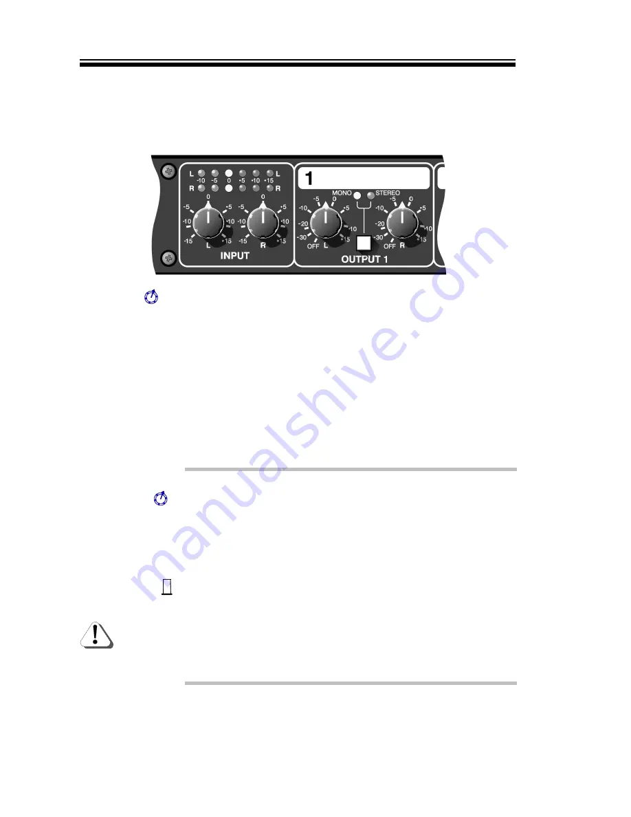
Input L&R
Used to set the optimal input gain for both Left and Right signals.
Use the display above to ensure the correct operating levels are
being attained. Adjustment in the range ±15dB is possible.
Separate controls are offered to permit the re-alignment of any
offset stereo image.
These controls also adjust the output level of the auxiliary ‘link’
jacks, which implies that any connected slave DA6 will only require
to have its input trims set to 0dB (vertically).
Input Display
Since the DA6 is normally used as a line amplifier, then it is quite
acceptable to ‘see’ signals in the positive gain region of this
display. However, ensure that the +15dB LED never illuminates
other than for brief instances, otherwise distortion will occur.
Output L&R
These controls should be used to set the optimal output level to
match the input section of the connected device, for both Left and
Right signals. Adjustment of ±15dB is possible. Normally, any
stereo image offset will have been corrected by the Left/Right input
controls. However separate output controls are also offered to give
total control of the stereo image.
Mono/Stereo
Selects whether the channel output is to be separate Stereo
signals or ‘summed’ to produce a Mono signal. If only one input is
used, this will be output to both sockets if Mono is selected.
Caution should be used when operating the DA6 with two similar
stereo signals that are out-of-phase with each other. Under such
conditions, using the Mono mode will produce very little usable
output. LEDs show the status of the switch.
Содержание DA 6
Страница 12: ...DA6 OPERATORS MANUAL BLOCK DIAGRAM...


