8
DRAWMER
1978 O
PERATOR’S
M
ANUA
L
H.F. Level
0 to 10
As the H.F. Level is increased the compressor’s side chain sensitivity to high frequencies is reduced, with the
result that less gain reduction is applied to those frequencies, creating the effect that the higher frequencies are
enhanced. It can be used to add definition, particularly to the human voice and acoustic instruments
.
In
Off / On
Switches the tonal shaping in and out (i.e. bypassing the sidechain) to allow for A/B comparisons between settings.
Note that Tonal Shaping and the rear panel sidechain Inserts work simultaneously and in conjunction with each
other - this provides an incredible amount of control over the compressor sidechain. If you wish to use the external
inserts only the shaping bypass switch should be out, so that the front panel shaping is not active but the inserts
are. Should you wish to use the front panel shaping only either disconnect the jacks from the insert connectors or
set the external unit into bypass.
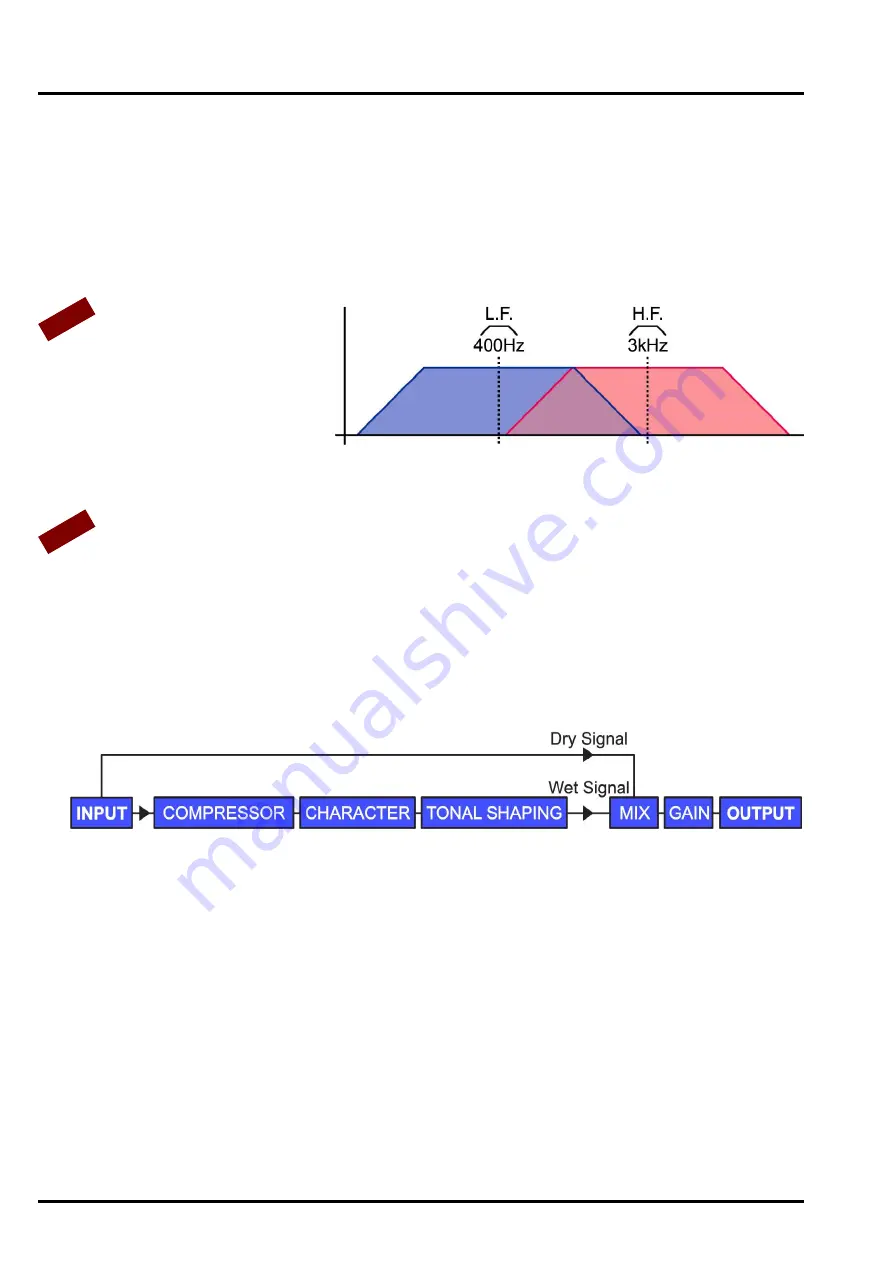
Because the shaping controls have bell
frequencies as well as shelf they cover
the full range of frequencies available
within the 1978, and thus, it is possible
to control the mid frequencies using just
the front panel shaping controls, without
the need for an external insert. If you set
the L.F. Frequency to 400Hz Bell and the
H.F. Frequency to 3kHz Bell you are effectively controlling the mid range with a wide bandwidth in just the same
way as you would control the L.F. and H.F. This could be used to adjust the overall balance of a mix, or on individual
instruments, to bring out the raspiness in a voice, for example.
As well as affecting the sidechain the shaping controls also add a small amount of E.Q. to the signal. This varies in
conjunction with the L.F. and H.F. Level controls - as these are set higher the E.Q. level also rises to a maximum
of +3dB when the level controls are in the 10 position.
This feature can be disabled using internal jumpers. Please contact [email protected] for details.
5 - OUTPUT
Mix
WET / DRY
A variable control that mixes a user defined amount of 'uncompressed' signal (dry) with the compressed signal
(wet) to create a 'parallel compression effect' without the need for external mixing devices. In this way the amount
of overall compression on the stereo signal is under complete control - set the 1978 to provide heavy compression
but then reduce the overall effect by mixing in some of the dry signal using the mix control.
Bypass
Off / On
A fully balanced hard-wire unit bypass connects the input directly to the output without alteration.
Note: To see the input level on the VU meters the Bypass switch should be on, as the meters display the level found
at the output.
Gain
-20 to +10dB
During compression the signal is attenuated, gain may be required to produce the required output level. Adjust so
that the output signal approaches the desired level only on signal peaks. The amount of gain required in order to
bring the signal level to the same is at input is displayed on the G.R. meter.
6 - VU METERS
Left / Right VU Meters
Two moving coil VU meters monitor the level of the output signal. Because the meter has VU characteristics, it
closely reflects what is actually being heard, though will not respond quickly enough to register short signal peaks.
Note that the meters are back lit yellow to aid reading in low light environments, however, as the Saturation is
increased the back light turns red to indicate the ‘warmth’ that the 1978 is creating.
+10dB Pad
0dB / +10dB
A two position switch adjusts the meters to show either normal output level, and for those working at ‘hot’ output
levels VU +10dB modes. i.e. with the switch at VU +10dB - when the VU meter reads 0dB the actual level is +10dB.
TIP
NO
TE


