background image

– 5 –

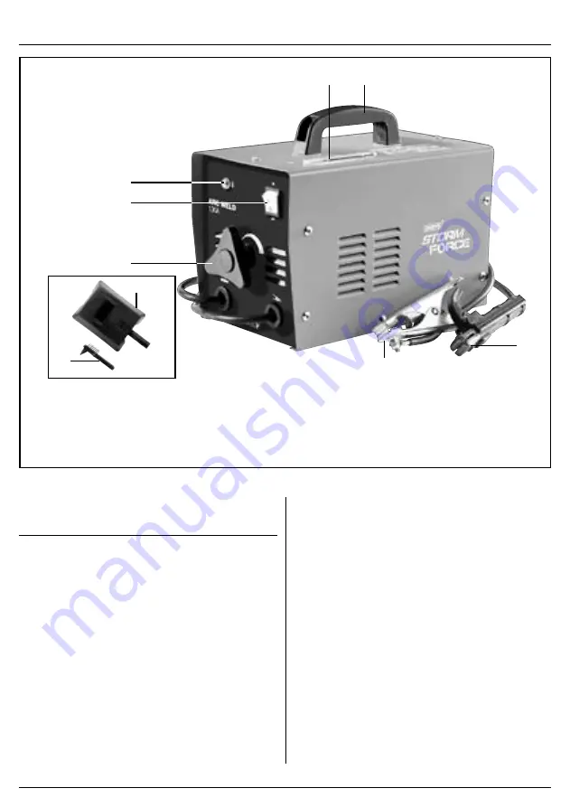
5.  IDENTIFICATION – FIG.A 


(1)

(2)

(3)

(5)

(8)

(9)

(7)

(6)

(4)

FIG.A

(1)

  Carry handle

(2)

  Welding current indicator

(3)

  On/off switch 

(4)

  Thermal overload indicator 

(5)

  Current adjustment control

(6)

  Electrode holder 

(7)

  Direct fit earth clamp

(8)

  Face mask

(9)

 Brush/hammer

6.  ASSEMBLING THE 

 WELDER 


Make sure the power supply information on the 

machine’s rating plate is compatible with the power 

supply you intend to connect it to.
A suitable plug must be fitted by a qualified 

electrician.
This machines wiring has insulation stripped in 

preparation for wiring a 16A plug (not supplied).
It is designed for connection to a 16amp


power supply 

rated at 230V AC.
Because it is constructed mostly of metal parts, it is a 

Class 1 machine; meaning, it must have an earth 

connection in the power supply. This is to prevent 

electrocution in the event of a failure.

NOTE: Remove the plug from the socket before carrying 

out adjustment, servicing or maintenance.
Check that the electrical supply delivers the voltage and 

frequency corresponding to the welding machine and 

that it is fitted with a delayed fuse suited to the maximum 

delivered rated current.
NOTE: The welding machines are set to the highest 

voltage at the factory.

6.1  PREPARING THE WELDING 

CIRCUIT

Connect the ground “lead” to the piece to be welded. 

Connect the welding electrode to the electrode holder.
When the machine is turned on and the electrode 

touches, the workpiece, the electrical circuit is complete, 

this will result in the welding arc being produced.

Содержание stormforce 53084

Страница 1: ... has been designed and contains all the necessary information to ensure its correct and safe use By following all the general safety instructions contained in this manual it will ensure both product and operator safety together with longer life of the product itself All photographs and drawings in this manual are supplied by Draper Tools to help illustrate the operation of the product Whilst every...

Страница 2: ...ation that draws attention to the risk of damage to the product or surroundings 1 3 EXPLANATION OF SYMBOLS Warning Read the instruction manual Warning Wear suitable welding eye face protection Warning Wear ear defenders During grinding operations Warning Wear protective gloves Keep out of the reach of children Warning Danger of electric shock Danger of fire Danger of explosion Danger of fumes Dang...

Страница 3: ...inuous wire replacing any parts in the torch or wire feeder carrying out maintenance operations or moving it use the carrying handle on the welding machine Do not touch any electrified parts with bare skin or wet clothing Insulate yourself from the electrode the piece to be welded and any grounded accessible metal parts Use gloves footwear and clothing designed for this purpose and dry non flammab...

Страница 4: ...n one welding machine has to be used on the same piece or in any case on pieces connected electrically the sum of the no load voltages on the electrode holders or on the torches may exceed the safety levels Make sure that an authorised expert evaluates the conditions beforehand to see if such risk exists and adopt the protective measures described in 5 9 of the IEX or CLC TS 62081 technical specif...

Страница 5: ...is constructed mostly of metal parts it is a Class 1 machine meaning it must have an earth connection in the power supply This is to prevent electrocution in the event of a failure NOTE Remove the plug from the socket before carrying out adjustment servicing or maintenance Check that the electrical supply delivers the voltage and frequency corresponding to the welding machine and that it is fitted...

Страница 6: ...operating temperature tr Cooling time running from thermal cutout tripping until the next reset with the transformer at the operating temperature A V Conventional welding current maximum and corresponding normalised voltage F POWER SUPPLY DATA U1 Input voltage permitted tolerance 10 I1 eff Effective absorbed current I1 max Maximum absorbed current G Weight H Safety symbols I Level of protection fr...

Страница 7: ...rning light switched on means that the thermal protection is running If the welding time tw indicated in the data plate is exceeded a thermal cutout stops operation before the welder is damaged Wait for operation to be resumed and if possible wait a few minutes more If the thermal cutout continues to cut in the welding machine is being pushed beyond its normal performance levels 8 3 RECOMMENDATION...

Страница 8: ...anty period is 90 days from the date of purchase The warranty is extended to 24 months for parts only This warranty does not apply to any consumable parts any type of battery or normal wear and tear nor does it cover any damage caused by misuse careless or unsafe handling alterations accidents or repairs attempted or made by any personnel other than the authorised Draper warranty repair agent Note...

Отзывы: