


Adjust Limits in User Mode
1.
Move motor to limit
(upper or lower)
to be changed. Screen must move
to previously set limit and will stop
automatically.
2.
Hold UP and DOWN buttons until motor
jogs.
3.
Move motor to its new limit location and
hold MY/STOP button until motor jogs.
Section 6 -
RF Remote Programming Instructions
(ONLY used if optional RTS Motor is specified)
IMPORTANT:
This section
ONLY
applies if optional RTS Motor has been ordered.
Please Note:
The motor ships with no programming. Follow these instructions to program unit to the desired transmitter.
1.
Select a transmitter channel to assign motor. Hold UP and DOWN
buttons until motor jogs, then release.
2.
Check motor direction. To reverse motor direction, hold MY/STOP
button for 5 seconds until motor jogs. Check direction again.
3.
Move motor to upper limit position. Hold MY/STOP and DOWN
buttons until motor moves down, then release. Use UP and DOWN
buttons to move screen to correct lower limit and press MY/STOP.
4.
While motor is at lower limit, hold UP and MY/STOP buttons until
motor moves up, then release. The screen should move to upper
limit and stop.
5.
Next, hold MY/STOP button until motor jogs.
6.
Put motor into USER MODE by holding small programming button
on the back of transmitter and waiting for motor to jog.
Setting an Intermediate Stop -
Screen MUST BE in USER mode.
1.
Move screen to desired mid-point location and
hold MY/STOP button until motor jogs.
2.
To test, press the MY/STOP button when
motor is standing still. The screen will move to
that intermediate location.
3.
To delete an intermediate stop, go to the
intermediate stop and hold the MY/STOP
button until motor jogs.
Add a Channel -
Screen MUST BE in USER mode.
1.
Select channel currently operating
motor, then hold programming
button until motor jogs.
2.
Select new channel to add to
motor, then hold programming
button until motor jogs.
3.
The motor should now work on
both old and new channel.
Delete a Channel -
Screen MUST BE in USER mode.
1.
Select channel operating motor
desired, then hold programming
button until motor jogs.
2.
Select channel to remove, then
hold programming button until
motor jogs. Motor should now
only work on channel kept from
Step 1.
Reset Motor
1.
Disconnect for 3 seconds,
reconnect for 10 seconds,
disconnect for 3 seconds.
Screen will roll.
2.
Hold program button on
remote and wait for 2
separate jogs.
Motor is now reset.
Section 5 -
Limit Adjustments
(Standard Motors)
Figure 7
"Down" Limit Adjustment
(requires
5/32
" (4mm) Allen wrench)
To Reduce Screen Drop:
1.
Raise screen surface approximately 1'
(30cm)
above desired setting and turn off.
2.
Turn DOWN
(I)
limit screw clockwise
(3 screw turns =
1/2
roller revolution)
.
3.
Test by lowering screen. Repeat steps 1 & 2 until desired position
is reached.
To Increase Screen Drop:
1.
Lower screen to down limit.
2.
With down switch on, turn DOWN
(I)
limit screw counterclockwise
(3 screw turns = 1/2 roller revolution)
to increase drop.
3.
Test by raising screen approximately 1'
(30cm)
then lower to new down limit.
4.
Repeat steps 2 and 3 until desired position reached.
Please Note:
For Quiet Motor with alternate limit screws:
WHITE screw = UP and RED screw = DOWN.
(Fig. 10)
.
"Up" Limit Adjustment
If Screen Raises Too High:
1.
Lower screen surface approx. 1'
(30cm)
below desired setting and turn off.
2.
Turn UP
(II)
limit screw clockwise
(3 screw turns = 1/2 roller revolution).
3.
Test by advancing screen up.
4.
Repeat steps 1 through 3 until desired position is reached.
If Screen Needs to Raise Higher:
1.
Lower screen surface approx. 1'
(30cm)
below desired setting and turn off.
2.
With UP switch on, turn UP
(II)
limit screw counterclockwise
rts
(3 screw turns =
1/2
roller revolution)
.
3.
Repeat steps 1 and 2 until desired position is reached.
CAUTION:
- Be sure all switches
are in “off" position
before adjusting limit
switches.
- Be prepared to shut off
manually while testing.
- Screen may be
damaged by lowering
it too far and
exposing roller.
- Motor must be
installed so that limit
switches are pointed
down.
Left hand motor:
White Socket—Down
Yellow Socket—Up
Right hand motor:
White Socket—Up
Yellow Socket—Down
Left hand motor:
White Socket—Up
Yellow Socket—Down
Right hand motor:
White Socket—Down
Yellow Socket—Up
Left hand motor:
White Socket—Down
Yellow Socket—Up
Right hand motor:
White Socket—Up
Yellow Socket—Down
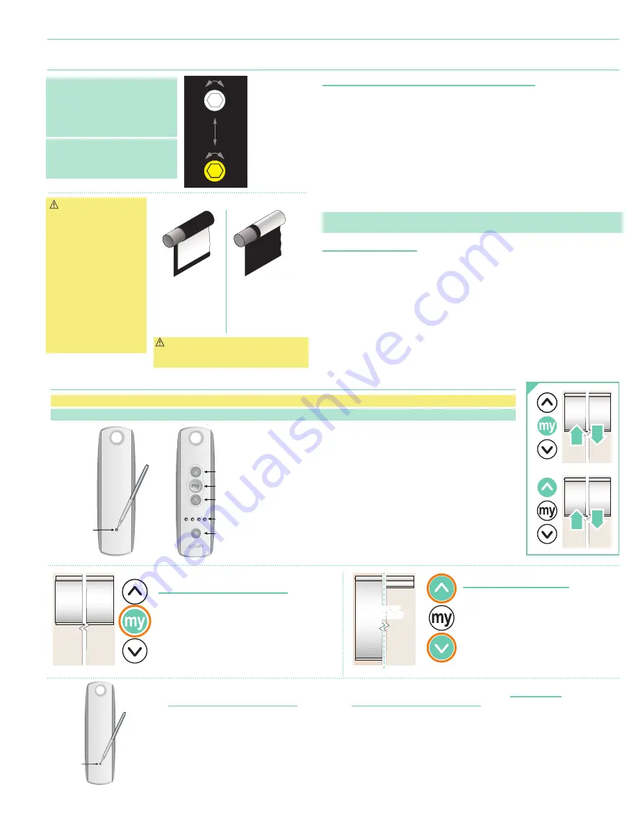
Waterfall Roll
Standard Roll
Motor
End
Audience
Side
Motor
End
Audience
Side
Reverse Roll
Motor
End
Back
Side
CAUTION:
DO NOT allow dowel to
wrap over roller when operating screen!
This could damage screen.
Figure 6
Please Note:
Screen limits
are factory set for optimum
performance. Any adjustment of
these limits could void the warranty.
Please check with Draper prior to
resetting screen limits.
Please Note:
If Screen is “Right
Hand Motor" the WHITE/DOWN
(I)
and YELLOW/UP
(II)
limit screws
are reversed
(Fig. 7)
.
lI
I
+
+
DOWN Limit (I)
Clockwise decreases
down
travel.
UP Limit (II)
Counterclockwise
increases
up
travel.
DOWN Limit
(I)
:
Clockwise
decreases
down
travel.
UP Limit
(II)
:
Counterclockwise
increases
up
travel.
Channel
Selector
UP
STOP
DOWN
LED Lights
BACK
Programming
Button
Pen
BACK
Programming
Button
Pen
upper or
lower limit
page 5 of 8
N E


