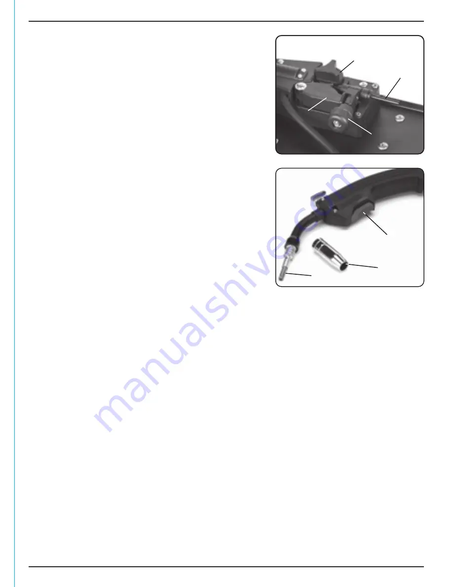
FIG.4
14
8. PREPARING THE WELDER
8.3 WIRE DRIVE UNIT – FIGS. 4 – 5
The wire is fed down the torch lining by the wire drive
motor. Tension of the rollers must be adjusted
correctly to prevent the filler wire slipping or jamming.
iv. Loosen tensioner
anticlockwise enough to
swing it outwards and lift arm
, moving the
tension roller
.
v. Trim 10cm of wire and discard it, before
flattening out the next 15cm. Do not let the
wire lose tension.
vi. Pass the filler wire through the guide
and
over the top of the drive roller fitted under
securing nut
. The drive roller comes with
two grooves for different wire gauges. Remove
nut to see the groove size that is
NOT
in use.
Note:
The wire must sit in the appropriate
groove for the wire gauge. The groove size is
etched on the side of the roller. To reverse the
roller, remove nut and flip the drive roller over
before refitting nut
.
vii. Make sure the wire is well inside the torch liner
before closing the arm
and tensioner
.
viii. Connect the welding machine to the power
supply. Position the switch to ‘on’.
ix. Unscrew/remove the gas shroud
and with
a small spanner unscrew and remove the tip
. Pull the trigger
and observe
the wire feed mechanism. If the wire is being fed correctly it will come out of the
swan neck. Pass the tip over the wire and secure back onto the swan neck. Do not over
tighten. Resecure the gas shroud and trim the wire back as required.
Note:
Ensure the tip size matches the wire size prior to installing.
FIG.5
Содержание MIG100GG
Страница 22: ...22 NOTES ...
Страница 23: ...23 NOTES ...


