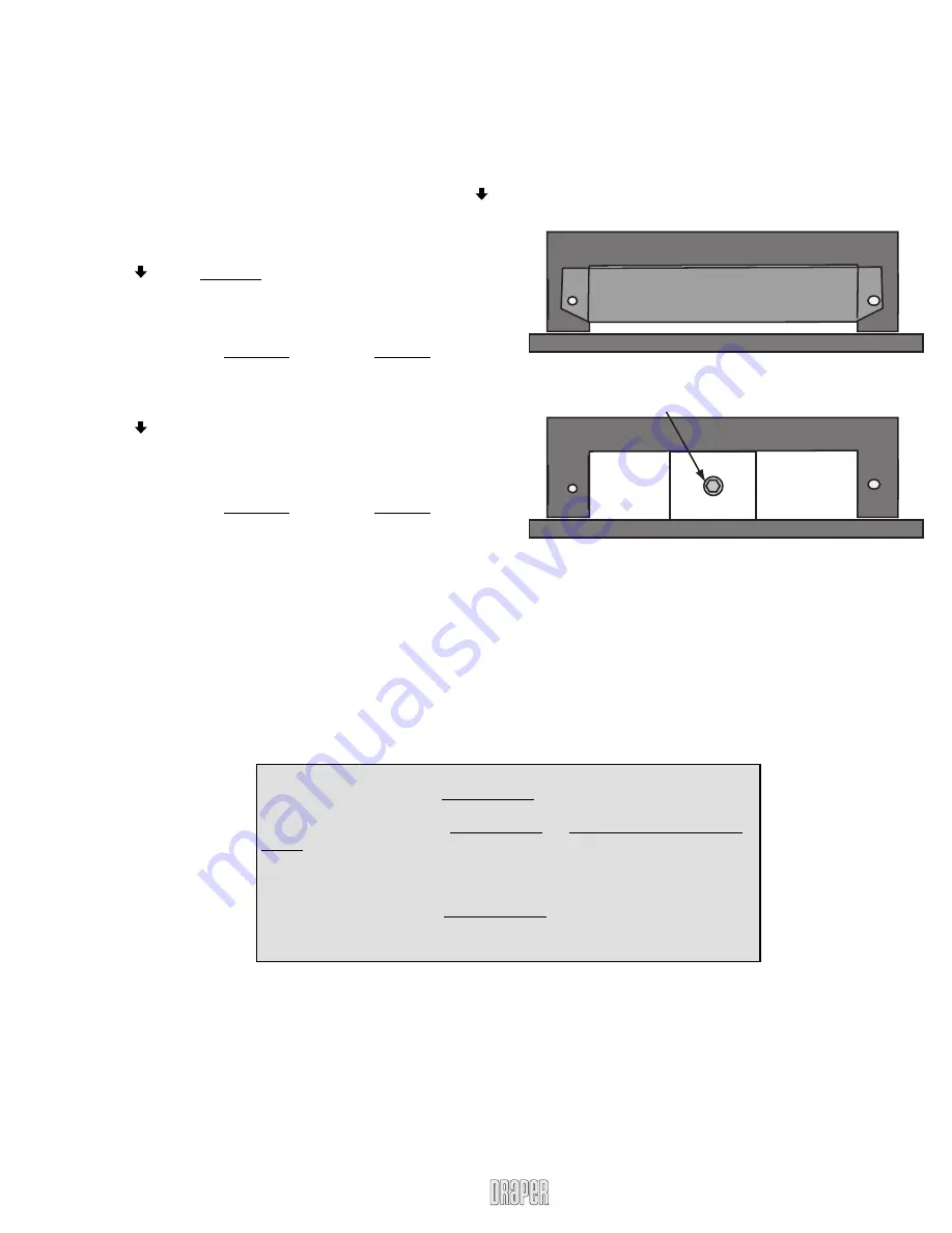
Manual Override (M8 socket required)
Manual Override Instructions
(Only available on FSL-F-42 and FSL-F-65)
If you lose power to the unit, it can be raised or lowered using the
manual override. To access the manual override, remove the metal panel
from the top of the lift. The unit can be raised or lowered by using an M8
socket to fi t the head of the threaded shaft to drive the lift up and down
with the manual override. You can use a regular ratchet or an electric
drill with M8 socket attached.
Flatscreen Lift by Draper, Inc.
page 7 of 7
www.draperinc.com
(765) 987-7999
Universal Infrared System Programming
The infrared system does not use any fi xed IrDA codes. It is capable of
learning any code you wish to assign to it. Below are instructions on how to
assign codes for up/down movement. The IR receiver only is supplied. Any IR
remote transmitter can be used.
First, unlock access to all controller functions:
Press and hold
“Setup”
button. While holding
“Setup,”
press and hold
button for fi ve seconds.
Ird – Assigning the button/code for downward movement.
Press
“SETUP”
button until
“Ird”
shows up on the display.
Press button. A single beep indicates that the system is ready for pro-
gramming.
Aim your infrared remote control at the infrared eye, which should be con-
nected to the infrared port on the bottom of your controller.
Press the remote control button you would like to designate for downward
movement. You will hear a double beep fi rst and then a triple beep once the
code is recognized and the task is fi nished.
Iru – Assigning the button/code for upward movement.
Press
“SETUP”
button until
“Iru”
shows up on the display.
Press button. A single beep indicates that system is ready for program-
ming.
Aim your infrared remote control at the infrared eye, which should be con-
nected to the infrared port on the bottom of your controller.
Press the remote control button you would like to designate for upward
movement. You will hear a double beep fi rst and then a triple beep once the
code is recognized and task is fi nished.
IrDA Interfacing Instructions
The fi rst RJ14 terminal from the left, marked as IrDA port, is provided to
plug in the infrared eye. IrDA eye shipped with our controller cannot be
coupled with any connecting block and used with fl ushers, as it generates TTL
(Digital) signal. The IrDA eye is connected to pins 3; 4; 5 on IrDA RJ11 termi-
nal. Only the eye provided with the controller can be connected to pins 3; 4; 5.
If you need to use alternative IrDA (Analog) eye, capable of working with
fl ushers, then you must connect it to the following pins on the same IrDA RJ11
terminal:
Pin 1: fl usher/IrD signal (+)
Pin 6: fl usher/IrD signal (-)
Troubleshooting Info:
A horizontal fl ashing bar in the
lower left corner
of the display tells you that the system
assumes that it is in the
lowest/closed position
.
If you fi nd the bar fl ashing in the
lower left corner
and the lift is not in the lowest/closed
position, use
“BYP”
function to bring the lift all the way down.
(You may fi nd yourself in this situation when “Up” and “Down” buttons on the controller are
used without previously connecting controller to the lift)
A Horizontal fl ashing bar in the
upper right corner
of the display shows you that the lift
has reached its maximum (previously programmed) extension height.
Use
“EP”
function to set new desired height.


