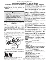


Case Dimensions
Fabric width + C
D
B
A
A
B*
C
D
Series E
127 mm
133 mm
305 mm
152 mm
Series V
152 mm
162 mm
varies
varies
*Add 29 mm to height if case is to be bevel style.
Tab-Tension Adjustment Procedure
Dowel
Adjustment
Screw
Tensioning
Cable
Draper’s Tab-Tensioning System is factory-set, and under normal
circumstances will not require field adjustment. If, however, you notice
wrinkles, waves or other indications that the tensioning cables need to
be adjusted, follow the procedure below.
1
Determine which side requires adjustment.
2
Secure dowel with one hand.
Caution: Do not touch or bend surface.
3
Using Phillips-head screwdriver, depress
spring-loaded adjustment screw and slowly
turn clockwise to tighten tension, or
counterclockwise to loosen tension. The
screw adjusts in ¼ turn increments. Adjust
only
one increment
(¼ turn) at a time
.
4
If problem is not corrected, leave screen in position
for 24 hours to allow surface material to stretch into position.
5
If problem still is not corrected, repeat steps 2 and 3.
220V Artisan Projection Screen by Draper
Page 2 of 2
www.draperinc.com
(765) 987-7999
Wiring Diagrams
MC1
See separate Serial Communica-
tion-RS232 Instruction sheet for
enabling RS232 with the MC1.
Low Voltage and Remote Control
Please Note: Do not wire motors in parallel.
Neutral
L1
220v,
50 Hz.
Dashed wiring
by installer
Control
switch
Single Station Control
CE Approved
Junction box at
left end of screen
Internal Screen Wiring
Blue-220v (Common)
Brown-220v (Down)
Black-220v (Up)
Dashed wiring
by installer
Neutral
Hot
Multiple Station Control
Not CE Approved
Cap off with wire
nut & tape
Red
Red
Red
Blue
Blue
Blue
Black
Black
220v, 50 Hz.
Black
Junction box at
left end of screen
Internal Screen Wiring
Blue-220v (Common)
Brown-220v (Down)
Black-220v (Up)
Green/Yellow (Motor Ground)
Green/Yellow (Motor Ground)
3 Button Wall Switch
DOWN - Black
COM - White
UP - Red
White or Blue-Common to screen & 110/220V AC Neutral
Red-to screen (directional)
Brown-to screen (directional)
Yellow-to 110/220V AC-Hot
Black-to 110/220V AC-Hot
Green/Yellow (Ground)
Eye Port
for IR Eye, RF Receiver or LED
Wall Switch. For more than one of
these, a splitter is required.
Aux Port
for connecting additional LVC-III
modules (up to six total can be linked-
connect from Aux to Eye).
Dashed wiring by electrician
Low voltage wiring by others
White/Blue (Common)
Red 110/Black 220 (Up)
Black 110/Brown 220 (Down)
Location of key
operated on-off
switch if furnished
To
110/220V
Line
Internal Screen Wiring
STOP
Control
Switches
24v DC
STOP
Green/Yellow
(Motor Ground)
RS232 Data FR
OM Control System
RS232 Data
TO
Control System
Signal Ground & Manual Switch Common Manual Switch Do
wn
Manual Switch Up
White or Blue-Common Red-to Screen (directional) Blac
k-to Screen (directional
)
Bro
wn-Hot to
AC
Green/Y
ell
ow
-Ground
Fuse
Program LED
Ey
e
Po
rt
for IR Ey
e.
F
or RF Recei
ve
r or LED
Wa
ll Switch, a Splitter and a
Po
wer Supply
is required
. Plug RF Receiv
er or LED
Wa
ll
Switch and
Po
wer Supply into splitter
, then
run cab
le from Splitter to MC1 Ey
e
Po
rt
.
Lo
w
Vo
ltage
Wi
ring
by
others
AC
Wi
ring
by
electr
ician
MC1
Location of
ke
y
operated on-off
sw
itch if fur
nished
To
AC
Line
White/Blue (Common) Red 110/Blac
k 220 (Up)
Blac
k 110/Bro
wn 220 (Do
wn)
Inter
nal
S
creen
Wi
ring
Green 110V/ Green/Y
ello
w 220V
(Motor Ground)


