

Installation/Operating Instructions
220V Artisan Series Electric Projection Screen
These Installation/Operating Instructions are available in the official language
of the country where you purchase the product. Please contact your distributor
to request a copy.
Vous pourriez demander les instructions d’installation et d’opération traduises
dans la langue officielle du pays ou vous achetez le produit. Veuillez demander
à votre distributeur.
Die Gebrauchsanweisung für Installation und Konstruktion sind in der offiziellen
Sprache des Landes, indem Sie das Produkt gekauft haben, vorhanden. Fragen
Sie die jeweilige Verkaufs-Abteilung.
Caution
1
Read instructions through completely before proceeding.
2
Follow instructions carefully. Installation contrary to instructions
invalidates warranty.
3
Screen should be accessible for complete removal should fabric become
damaged or should other service be required.
4
Screen should be installed level (using a carpenter’s level).
5
Nothing should be fastened to screen dowel or viewing surface.
6
Operating switch(es) packed separately in screen carton. Do not discard
with packing material.
7
Screen operates on 220V AC, 50 Hz., 1 ph. current.
NOTE: Screen has been thoroughly inspected and tested at factory and
found to be operating properly prior to shipment.
Hanging Screen
General
When locating viewing surface and checking clearance for screen’s operation,
remember surface is centered in case. Take care to install wall/ceiling electrical
box and conduit so they will be fully concealed by the screen case after installation.
Handle case carefully to protect its finish. Regardless of mounting method, screen
should be positively and securely supported so that vibration or even abusive pulling
on the viewing surface will not cause case to work loose or fall. Installer must insure
that fasteners used are of adequate strength and suitable for the mounting surface
chosen.
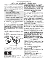
Wall Mounting
Mount 2, 3, or 4 aluminum brackets provided on the wall at desired height, using toggle
bolts provided or other appropriate fasteners. Verify that they are in line and level to
fully engage matching brackets pre-installed on back of screen case. When screen
is set on brackets, pull down gently to ensure that it is snug and secure.
Ceiling Mounting
Install through the two 24 mm diameter mounting holes at each end of the screen
case, using appropriate fasteners.
Copyright ©2014 Draper Inc.
Form ArtisanE&V220V_Inst14
Printed in U.S.A.
If you encounter any difficulties installing or servicing your Artisan Series screen, call your dealer
or Draper, Inc. Spiceland, Indiana, U.S.A., telephone (765) 987-7999 or fax (765) 987-1689.
Electrical Connections
Screen operates on 220V AC, 50 Hz., 1 ph. current. .75 amp current draw. Duty
Cycle: On 28 seconds/Off 4 minutes. Junction box is located inside left endcap and
cover plate is secured to endcap with two screws.
Junction box contains brown,
black and blue pigtail leads and green internal ground wire, per wiring diagram on
reverse
.
Wall or ceiling electrical box should be installed so as to be fully concealed by
screen case after installation. Conduit openings are covered by plastic caps (to
be removed for installation). Opening for ceiling mounting is located in top, 73 mm
from the end and 64 mm from the back of the case. Opening for wall mounting is in
back, 73 mm from the end and 70 mm from the top of the case.
Screen is shipped with internal wiring complete and control switch(es) fully boxed.
Wire connecting screen to switch(es) and switch(es) to power supply should be
furnished by installer. Connections should be made in accordance with attached
wiring diagram, and wiring should comply with National and local electrical codes.
All operating switches should be “Off” before power is connected.
Operation
Series E:
Before operating screen remove tape securing fabric and dowel to roller.
If viewing surface hangs out of case 20 to 23 cm, tape has probably been broken
by rough handling in shipment, allowing surface to “unwrap” one turn about the
roller. Manually wrap the fabric back around the roller without turning the roller
itself.
Series V:
Important Instructions—The shipping support brackets must be removed
from each end of dowel during initial operation before screen is operated in UP
direction. After screen is installed, run viewing surface DOWN to access screws
that hold brackets to dowel. Loosen hex head screw, remove bracket and retighten
screw at each end of dowel. Cycle viewing surface down and up several times to
confirm satisfactory operation. If viewing surface does not operate properly, turn
power off and check electrical connections.
220V Single Station Control
—3-position up-off-down switch permits operation to
be stopped at any point. Factory adjusted limit switches automatically stop screen
when fully down or fully up.
220V Multiple Station Control (Not CE approved)
—Switches are similar in
appearance to 220V Single Station Control. Screen stops when switch is released
and may be restarted in either direction. Factory adjusted limit switches stop
screen automatically when fully down or fully up.
24V Control
—Three-button up-stop-down switch(es) stop at any point desired,
operate in any sequence. Factory adjusted limit switches automatically stop screen
when fully down or fully up. Installer should incorporate an all-pole disconnect in
the fixed wiring.
Key Operated Switching (Not CE approved)
—Two kinds of key-operated switch-
es are optionally available with this unit.
1
The key-operated power supply switch
controls power to the screen and switches. When it is “off”, the switches will not
operate screen. Key may be removed from the switch in either “on” or “off” position.
2
A three-position key switch permits the screen to be operated directly by key. In
this case, the screen’s operator must always have a key.
RS232/Ethernet—
Serial communication and network communication optionally
available with wall switches, RF or IR remote.
Z-brackets supplied
with screen for
wall mounting.
Hardware by others.
Z-brackets on
rear of case
Screen Case
Knockout for rear
conduit connection
Left end
24 mm holes for
ceiling mounting.
2 each end.
Ceiling mounting hardware
by others
Wall
Knockout for top
conduit connection
®
These instructions are meant as a guide only. They do not imply any responsibility on
the part of the manufacturer for improper installation or faulty workmanship at the jobsite.
Limit Adjustments
Please Note: Screen limits are factory set for optimum performance of the
screen. A procedure is outlined below for minor tweaks, but any adjustment
of these limits may negatively affect the flatness of the screen surface and
could also void the warranty. Please check with Draper prior to resetting
screen limits.
CAUTION: Always be prepared to shut screen off manually when new
adjustment is being tested. Screen may be severely damaged if viewing
surface is allowed to run too far up or too far down.
C
AUTION: Be sure all switches are in “off” position before adjusting limit
switches.
The motor limit screws are normally located on the audience left of screen roller.
"DOWN" LIMIT ADJUSTMENT
To Reduce Screen Drop
1
Raise screen surface about 30 cm (1') above desired setting and turn off.
2
Turn the DOWN limit screw (White or (I)) clockwise (three screw turns = ½ roller
revolution).
3
Test by running screen down and repeat steps 1 and 2 until desired position is
reached.
To Increase Screen Drop
1
Run screen to the down limit.
2
With the down switch on, turn the DOWN limit screw (White or (I)) limit screw
counterclockwise (three screw turns = ½ roller revolution) to increase drop.
3
Test by running screen up about 1' and back down to new down limit.
4
Repeat steps 2 and 3 until desired position is reached.
"UP" LIMIT ADJUSTMENT
Screen is Running Too Far Up
1
Lower screen surface about 30 cm (1') below desired setting and turn off.
2
Turn the UP limit screw (Yellow or (II)) clockwise (three screw turns = ½ roller
revolution).
3
Test by running screen up.
4
Repeat steps 1 through 3 until desired position is reached.
Screen Needs to Run Up More
1
Run screen down about 1' and turn off.
2
With the up switch on, turn the UP limit screw (Yellow or (II)) limit screw
counterclockwise (three turns of screw = ½ roller revolution).
3
Repeat steps 1 and 2 until desired position is reached.
CAUTION: Do NOT allow the dowel to wrap up over the roller when the
screen is running up! This could damage the screen.


