background image

– 15 –

9.  OPERATION & USE

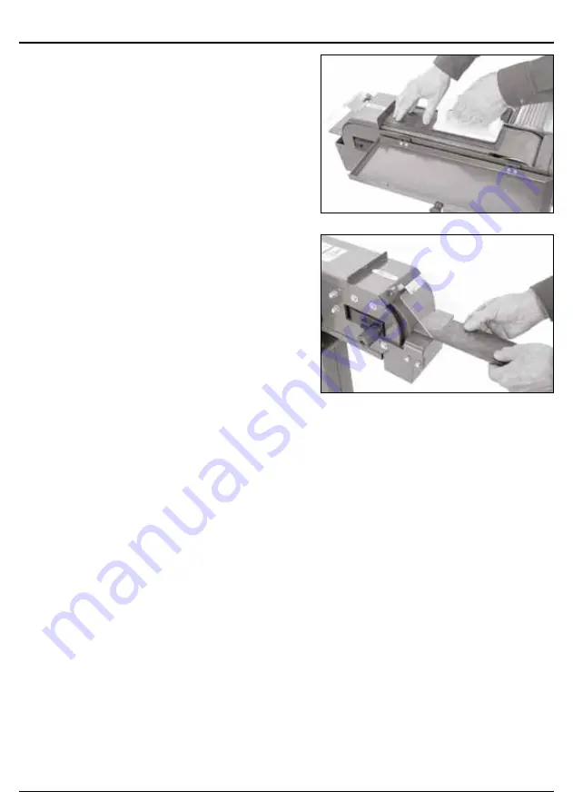
9.3  FLAT GRINDING – FIG.11

Flat grinding operations can be performed directly 

on the belt against the platen. Always use two 

hands to control the workpiece and use the work 

stop to support it.
–  Connect the machine to the power supply, turn 

it ON and allow it to reach full speed.

–  While supporting the workpiece against the 

work stop, slowly feed it into moving belt with 

light even pressure. Use a push block to 

maintain control of the workpiece. DO NOT 

force the workpiece against the belt.

Caution! The moving belt can cause serious 

personal injury if it comes in contact with fingers, 

hands or other body parts. Use extreme care to 

provide a safe distance between the belt and any 

part of your body.

9.4  END GRINDING – FIG.12

End grinding operations are performed on the front 

end of the grinder with the workpiece pressing 

against the contact wheel. For additional control 

over the workpiece, use the work rest to support 

workpieces during operations. Always use two 

hands to maintain best control.
–  Connect the machine to the power supply, turn 

it ON and allow it to reach full speed.

–  Position workpiece on work rest if feasible.
–  Use both hands to maintain control of the 

workpiece and slowly feed it into the contact 

wheel at the end of the moving belt, with light, 

even pressure. DO NOT force the workpiece 

against the belt.

Caution! The moving belt can cause serious 

personal injury if it comes in contact with fingers, 

hands or other body parts. Use extreme care to 

provide a safe distance between the belt and any 

part of your body.

9.5  SAFETY NO VOLT SWITCH

This machine is fitted with a safety ‘no volt switch’. 

Lift cap to access standard on and off switch, if the 

no volt stop button has been used to stop the 

machine.

FIG.11

FIG.12

Содержание 98421

Страница 1: ... the product has been designed and contains all the necessary information to ensure its correct and safe use By following all the general safety instructions contained in this manual it will ensure both product and operator safety together with longer life of the product itself All photographs and drawings in this manual are supplied by Draper Tools to help illustrate the operation of the product ...

Страница 2: ...neral Fax 44 0 23 8026 0784 1 3 UNDERSTANDING THIS MANUAL S SAFETY CONTENT Warning Information that draws attention to the risk of injury or death Important Information that draws attention to the risk of damage to the product or surroundings 1 4 COPYRIGHT NOTICE Copyright Draper Tools Limited Permission is granted to reproduce this publication for personal and educational use only Commercial copy...

Страница 3: ...2 ADDITIONAL SAFETY INSTRUCTIONS FOR ABRASIVE FINISHING MACHINES 8 5 3 RESIDUAL RISK 9 5 4 CONNECTION TO THE POWER SUPPLY 9 6 TECHNICAL DESCRIPTION 6 1 IDENTIFICATION 10 7 UNPACKING AND CHECKING 7 1 PACKAGING 11 7 2 WHAT S IN THE BOX 11 8 ASSEMBLY INSTRUCTIONS 8 1 SUPPORT COLUMN 98422 ONLY 12 8 2 INSTALLATION 12 8 3 EYE SHEILD 13 8 4 SPARK TRAP 13 8 5 WORK REST 13 9 OPERATION AND USE 9 1 REPLACING...

Страница 4: ...2 CONTENTS 4 11 DISPOSAL 12 1 DISPOSAL 18 12 EXPLANATION OF SYMBOLS 13 1 EXPLANATION OF SYMBOLS 19 ...

Страница 5: ...when the warranty period is 90 days from the date of purchase This is extended to 24 months for parts only This warranty does not apply to any consumable parts any type of battery or normal wear and tear nor does it cover any damage caused by misuse careless or unsafe handling alterations accidents or repairs attempted or made by any personnel other than the authorised Draper warranty repair agent...

Страница 6: ...nd pressure level 81 7dB A Sound power level 94 5dB A Weight 26kg 4 3 HANDLING AND STORAGE Care must be taken when handling this product Dropping this power tool could have an effect on its accuracy and could also result in personal injury This product is not a toy and must be respected Environmental conditions can have a detrimental effect on this product if neglected Exposure to damp air can gra...

Страница 7: ...s properly Loose clothing long hair and jewellery are all dangerous because they can become entangled in moving machinery This can also result in parts of body being pulled into the machine Clothing should be close fitted with any long hair tired back and jewellery and neck ties removed Footwear must be fully enclosed and have a non slip sole Wear personal protective equipment PPE Dust noise vibra...

Страница 8: ...local standards and as such should be maintained and repaired by someone qualified using only original parts supplied by the manufacturer This will ensure the tool remains safe to use 5 2 ADDITIONAL SAFETY INSTRUCTIONS FOR ABRASIVE FINISHING MACHINES WARNING Failure to follow these rules may result in serious personal injury Don t operate the machine until it is assembled and installed according t...

Страница 9: ...nce is supplied with a moulded 3 pin mains plug for your safety The value of the fuse fitted is marked on the pin face of the plug Should the fuse need replacing ensure the substitute is of the correct rating approved to BS1362 and ASTA or BS Kite marked ASTA BSI The fuse cover is removable with a small plain slot screwdriver Ensure the fuse cover is replaced before attempting to connect the plug ...

Страница 10: ...ttons emergency stop switch 3 Work stop 4 Work rest 5 Belt tracking adjustment knob 6 Spark trap 7 Eye sheild 8 Belt guard 9 Belt access panel 10 Contact wheel 11 Platen 12 Belt tension lever 13 Drive wheel 14 Dust extraction outlet 10 9 9 14 13 3 11 12 8 7 6 4 1 5 2 ...

Страница 11: ...ained at least during the warranty period in case the machine needs to be returned for repair Warning Some of the packaging materials used may be harmful to children Do not leave any of these materials in the reach of children If any of the packaging is to be thrown away make sure they are disposed of correctly according to local regulations 7 2 WHAT S IN THE BOX As shown below there are several p...

Страница 12: ...machine Position the column upside down and attach the base with the nuts bolts and washers removed in the previous step Then position right side up Remove the four bolts and washers from the top of the column Position machine on top of column and attach using the fasteners removed in previous step 8 2 INSTALLATION Before the machine can be used a suitable location must be found The area must be f...

Страница 13: ... 8 4 SPARK TRAP FIG 6 To install the spark trap Install the spark trap into the slot beneath the contact wheel Tighten the knob to secure position 8 5 WORK REST FIG 7 To install the work rest Remove the two bolts and washers already installed into the work rest Position the work rest in place and install using fixings just removed 13 8 ASSEMBLY INSTRUCTIONS FIG 4 FIG 5 FIG 6 FIG 7 ...

Страница 14: ...ng is to make sure the belt stays centered on the wheels and platen during grinding operations It needs to be checked any time you change or replace the belt Warning Never attempt to adjust maintain or service this machine while it is connected to the power supply To check and adjust the belt tracking Open the belt access panel Standing at the rear of the machine rotate the drive wheel 13 with one...

Страница 15: ...formed on the front end of the grinder with the workpiece pressing against the contact wheel For additional control over the workpiece use the work rest to support workpieces during operations Always use two hands to maintain best control Connect the machine to the power supply turn it ON and allow it to reach full speed Position workpiece on work rest if feasible Use both hands to maintain contro...

Страница 16: ...void blocking the air inlets and vacuum the ventilation slots regularly 10 2 TROUBLESHOOTING Problem Possible Cause Remedy Motor does not start or power supply trips immediately after start up 1 Emergency stop button depressed at fault 1 Lift switch cover Press ON button 2 Incorrect power supply voltage or circuit size 2 Ensure correct power supply voltage and circuit size are used 3 Power supply ...

Страница 17: ...p environment 1 Replace damaged belt Store in a cool dry area 2 Belt has been broken or folded 2 Replace damaged belt Do not bend or fold belt 3 Belt is old 3 Replace with new belt Belt tracks to one side under load 1 Belt tracking not set correctly 1 Reset belt tracking Belt clogs quickly 1 Excessive pressure while grinding 1 Clean belt and then reduce workpiece pressure 2 Belt worn or damaged 2 ...

Страница 18: ...that it is disposed of according to national regulations Contact your local authority for details of collection schemes in your area In all circumstances Do not dispose of power tools with domestic waste Do not incinerate Do not dispose of WEEE as unsorted municipal waste Waste Electrical Electronic Equipment 18 ...

Страница 19: ...s Wear protective gloves WEEE Waste Electrical Electronic Equipment Do not dispose of Waste Electrical Electronic Equipment in with domestic rubbish Disable the machine before attempting to maintain it Do not touch the belts while the machine is turning Risk of electric shock Do not remove cover WARNING Always follow instructions stated ...

Страница 20: ...ty Repair Agent For aftersales servicing or warranty repairs please contact the Draper Tools Help Line for details of an agent in your local area YOUR DRAPER STOCKIST TACM0620 Published by Draper Tools Limited No part of this publication may be reproduced stored in a retrieval system or transmitted in any form or by any means electronic mechanical photocopying recording or otherwise without prior ...

Отзывы: