background image

RACK MOUNTING
Adequate ventilation is very important in multichannel
installations.  Units should be spaced apart by at least
one panel height wherever possible, and some air
movement is advisable in enclosed rack cabinets.
Excessive heat will shorten component life and modulator
performance will be degraded without proper cooling.

USE WITH A STEREO ENCODER
An external BTSC stereo encoder may be used with the
VM2551.  To sett the VM2551 for a flat audio response
that will accept the BTSC composite stereo input - remove
the top cover of the VM2551.  Observing the PCB that
contians the Audio, Video, A/V Ratio, and other compo-
nents, locate the small slide switch - SW2.  Set switch
SW2 to the Pre-emphasis OFF position.  The factory
default setting is Pre-emphasis ON - for mono operation.

CONNECTIONS AND CONTROLS
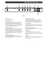
All connections to and from the VM2551 are made
through the rear panel.  Additional channels can be
added by using additional VM2551 modulators and either
multi-port combiners or combinations of two-port
combiners.

INSTALLATION NOTES
Level adjustment provides optimum performance in
multichannel installations.  The modulator outputs should
be checked periodically to maintain a ±1 dB variation of
adjacent channel carriers.  Aural/Visual (A/V) ratios
should be held to -15 dB or less.  The output 'RF Level'
and 'A/V Ratio' controls are used respectively to make
these adjustments.  If an output level of less than
+40 dBmV is required, add an attenuator of the
appropriate value to the modulator output.

6     Installation

Содержание VM2551

Страница 1: ...Instruction Manual is a registered trademark of the R L Drake Company Copyright 2005 R L Drake Company P N 3852551B 12 2005 VM2551 Commercial Video Modulator For use in NTSC systems...

Страница 2: ...y purpose of the polarized plug Alternate Warnings If this product is equipped with a three wire grounding type plug a plug having a third grounding pin the plug will only fit into a grounding type po...

Страница 3: ...can can be inserted via the rear panel 4 5 MHz input These features combined with a carefully designed low intermodulation output stage provide reliable operation in a densely crowded SMATV or cable e...

Страница 4: ...range from 12 to 18 dB below the visual carrier The aural carrier should be adjusted to approximately 15 dB below the visual carrier normal operation F2 F3 AUDIO LEVEL Control Audio Overmodulation LE...

Страница 5: ...rrier output level is 40 dBmV R4 VIDEO INPUT Connector This is the baseband video input to the IF circuits This input accepts baseband through 4 2 MHz video at levels from 0 7 Vp p to 1 5 Vp p R5 AUDI...

Страница 6: ...switch SW2 Set switch SW2 to the Pre emphasis OFF position The factory default setting is Pre emphasis ON for mono operation CONNECTIONS AND CONTROLS All connections to and from the VM2551 are made th...

Страница 7: ...ance Pre emphasis Frequency Response Total Harmonic Distortion Hum and Noise 4 5 MHz INPUT Internal Jumper Change to Activate Input Level COMPOSITEIF LOOP IF Frequency Loop Level Loop Impedance GENERA...

Страница 8: ...be on file at R L DRAKE you will need to send proof of purchase to receive warranty service Typically a copy of the invoice from an R L DRAKE dealer will suffice The warranty is for the original owner...

Страница 9: ...enance repair anduseareimportanttoobtainproperperformancefromthisproduct Thereforecarefully readtheInstructionManual ThiswarrantydoesnotapplytoanydefectthatR L DRAKECOMPANYdeterminesisdue to 1 Imprope...

Страница 10: ...R L Drake Company 230 Industrial Drive Franklin Ohio 45005 U S A Customer Service and Parts Telephone 1 937 746 6990 Telefax 1 937 806 1576 World Wide Web Site http www rldrake com...

Отзывы: