Operating Instructions - From Drake Digital Headend
Control Program
1) Confirm that all connections to the MEQ1000A and its
installed encoder modules have been made as described
previously. Connect a serial cable from the RS232 IN
connector on the MEQ1000A to the serial port on the PC. (This
discussion assumes that the Headend Control Program has
already been installed on the PC as per the instructions
supplied with the software.)
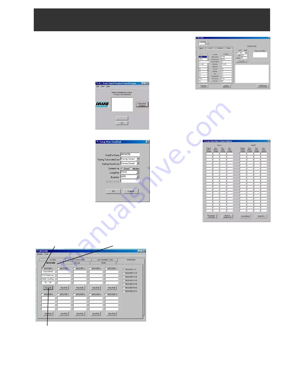
2) Activate the software. You
should see a screen similar to
FIGURE 1
at right.
3) Click on the ‘Setup New
Headend’ button. This will
bring up the screen shown in
FIGURE 2
. Type in the name
of the headend in the
‘HeadEnd Name’ field. In this
case we have typed in
MEQ1000A. Then select the
‘PC Baudrate’ and ‘Using
Port’. If you intend to use a
modem instead of a direct
connection, make that
selection using the ‘Connect
via:’ radio buttons, and type in
the phone number of the
desired modem in the ‘Number
to dial’ window. Then click
‘OK’.
4) You will be presented with
a screen similar to the one
shown on
FIGURE 3
. Click on the MEQ1000A tab, and click
on the box representing the MEQ1000A unit ID of the unit you
are programming. In this example we selected Unit ID #1.
Then click on the ‘View Edit” button.
This will bring up the screen shown in FIGURE 4. Click on
the Transcoder box and select the transcoder number you
wish to program. In this case we have selected Transcoder
1. Then select 'Input A' and select the number of the encoder
Operating Instructions
13
(from Drake Digital Headend Control Program)
Figure 1
Figure 2
Select MEQ1000A Unit ID MEQ1000A Tab
Figure 3
you choose to
program. In this
case, 'Input A'
contains an SDE24
which contains two
encoders. Select
radio button '1' and
program each
parameter to the
desired value.
Select radio button
2 and set each para-
meter to the desired value. Select in turn, 'Input B', 'Mux Setup
and 'Output' and set each parameter as described previously.
Note that if the value of the parameter selected in the left column
differs from the value of that parameter in the right column, that
value will appear in red.
6)
Click on the ‘Set Major/Minor Channel Numbers’ button.
You will be presented with a screen shown in FIGURE 5.
7)
This screen allows
the user to reasign
MPEG numbers as
well as new major and
minor channel
numbers.
8)
Once the selections
have been
made, click on the
‘Download to
MEQ1000’ button.
This will transfer all
selections on this
screen as well as all
selections made on
the previous screens
to the MEQ1000A and
its installed modules.
Close this screen by clicking on the ‘X’ in the upper right
hand corner of the screen.
9)
You will note that all of the items in the right hand columns
in the 'Input A', 'Input B', 'Mux Setup' and 'Output Encoders',
screens are now black and agree with the selections made in
the left hand columns.
10)
Additional information on the operation of the Drake
Digital Headend Control Program can be found in the
instructions included on the program CD.
Figure 4
Figure 5
View / Edit Button


