background image


Copyright © 2001-2018, Dr Robot Inc.  All Rights Reserved.

    www.DrRobot.com              

     V.03.02.18.Q                   

- 11 - 

III.


Operation of Jaguar Robot  

End user could develop his own Jaguar control program using the supplied development API and tools. Here, we 
will show you how to control the robot using the included “Jaguar Control Program” (Note: You need to install 
Google Earth program and other third party program first). 

Turn on/off the Platform 

Please follow the steps below to power up the robot. 

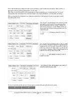
1. Turn to release the red button.  

2. Press and hold the start button for about 1 second, then release. 

    If you see the green LED on the start button is on, the system is powered up. 

    If not, please check the battery to make sure it is fully charged. 


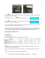
* To power off the robot, push down the red button, the system will shut down. 


Using Dr Robot Jaguar Control Program 

After  turn  on  the  robot,  please  make  sure  your  PC  could  find  the  WiFi  network  with  SSID  “DriJaguar”,  and 
connect with this network with key “drrobotdrrobot”.  After successful connection, please fix your PC IP address 
as “192.168.0.104” at this wireless interface. You could try to ping the main control module by command “ping 
192.168.0.60” to make sure the connection work well. 


This  program  will  demonstrate  how  to  control  and  navigate  the  Jaguar,  move  the  flipper  arms  and  how  to 
interpret, process, display and log multi-sensor information. This program is provided with source code (c#). 


updates motor encoder reading, motor temperature, board voltage and battery voltage measured 

at 10Hz; 


reads and displays IMU and Laser Range sensor data; 


displays GPS readings on the Google Earth; 


displays and controls camera. 


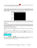
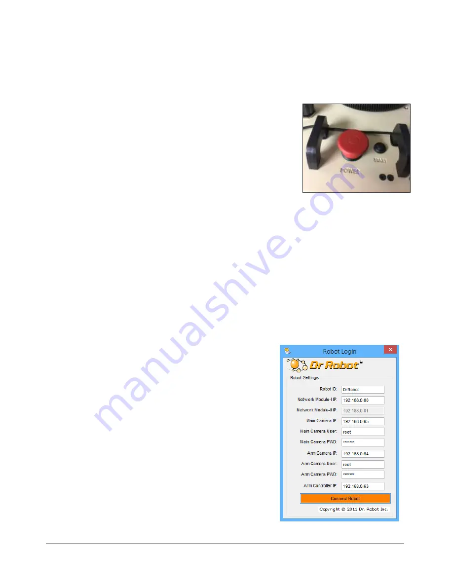
Once you start this program, you will see a “Login Window” 


Содержание Jaguar V6

Страница 1: ...t 2001 2018 DrRobotInc AllRightsReserved www DrRobot com V 03 02 18 Q All Terrain Autonomous Navigation Robot with GPS IMU JaguarV6withManipulatorArm User Guide Install Fuse Charge the battery pack be...

Страница 2: ...er draining the battery such as keeping the robot on without charging will damage the battery Neverpositionyourfinger s inbetweenthetrackand orarm smovingparts evenwhenthepowerisoff Therobotarms mustb...

Страница 3: ...panying with Dr Robot s product are solely owned and copyrighted by Dr Robot End users are authorized to use for personal research and educational use only Duplication distribution reverse engineering...

Страница 4: ...t 9 Overlook 9 Operation Scenario 10 Software Installation 10 III Operation ofJaguarRobot 11 Turn on off the Platform 11 Using Dr Robot Jaguar Control Program 11 Recharging 19 IV HardwareandElectronic...

Страница 5: ...rticulated sensor platform Integrated software features independent joint space control as well as gripper Cartesian space control While it only has 3 rotation joints excluding gripper when working to...

Страница 6: ...andmark GPS Optional Sealed weather resistant enclosure Temperature 30 to 50 Shock resistant chassis Motion and sensing controller PWM Position and Speed Control 5Hz GPS and 9 DOF IMU Gyro Acceleromet...

Страница 7: ...down Max 80W 450Kg cm Rated current 2 75A Max current 16A Height 400mm 15 7 manipulator at rest Width 700mm 27 6 Length 980mm 38 5 extended arms 640mm 25 2 folded arms Weight 41Kg Standard Configurat...

Страница 8: ...r with 5Hz Update Rate and WAAS 1 IMU9002 9 DOF IMU Gyro Accelerometer Compass 1 WRT802N 802 11N wireless AP router 1 BPN LP 20 22 2 V 20 AH LiPo Battery Pack 1 LPBC5000 2A LiPo Battery Charger 2 GPC0...

Страница 9: ...identify on the Jaguar V6 robot Jaguar V6 with Manipulator Arm Platform with Options Handle Bar Options Power Switch Outdoor GPS Joint 2 Front Camera Front Laser Scanner Headlights Front Arm Track Dri...

Страница 10: ...l the operator under any outdoor lighting environment even under direct sunshine The included Jaguar Control program will therefore be projected on the head mounted display where you could see all the...

Страница 11: ...the red button the system will shut down Using Dr Robot Jaguar Control Program After turn on the robot please make sure your PC could find the WiFi network with SSID DriJaguar and connect with this n...

Страница 12: ...not get the correct Latitude and Longitude position by clicking on map before the map loading is finished When loaded click OK button FlyToSetPoint button will bring you to the location latitude longi...

Страница 13: ...the motor driver board is in the Estop state due to the safety reason You need use EStopWheel button to release the motor driver board from emergency stop state You also need switch to FlipArm tag an...

Страница 14: ...pper Arm down Z Set Flipper Arm initialize position X Set front flipper arm to same position M Set Rear flipper arm to same position E Set Front flipper arms to up 30 degree D Set Front flipper arms t...

Страница 15: ...tion After powering up the robot or when the actual arm position is different from the arm position window shown on the right you should reset the arm track flipper arm position as following drive the...

Страница 16: ...you need to stop the robot when voltage is below marked voltage 22 2V in order to prevent battery damage Motor temperatures are also displayed here Encoder Pos boxes show the encoder position values...

Страница 17: ...he information about the front rear flip arm motors and the state of the flip arm motor driver board Arm tag shows Joints Angle Information and Control Value Arm J4 is Gripper It would be better if yo...

Страница 18: ...r1 tab will display motor driver controller 1 states for Joint 1 and 2 If you did not get the sensor reading back you could click QueryCmd button to send query command Please make sure the channel 1 a...

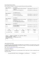
Страница 19: ...gram again Recharging Jaguar robot uses high performance LiPo batteries Extreme caution is needed when dealing with this type of battery explosion and damage could occur Please read the Charge Station...

Страница 20: ...and error message maintenance and safety message please refer to Intelligent Digital Balance Charger Operation Manual IV HardwareandElectronics NetworkSettings Wireless Router Setting The on robot pr...

Страница 21: ...o flow control Ethernet Module 4 192 168 0 62 Port 1 Port 10001 Manipulator Arm Joint pan Tilt motor driver board TCP 115200 8 N 1 no flow control Port 2 Port 10002 reserved TCP 115200 8 N 1 no flow c...

Страница 22: ...DOF IMU Gyro Accelerometer Co mpass GPS Module Camera AV Wireless AP Router LAN Power 12V Power 5V Antenn a Head Lights DC DC Power Board 5V 5V 5V 3 3 V Contr ol Port Powe r IN Chargi ng Plug ON LiPo...

Страница 23: ...r 5V Motor Control Channel 0 Channel 0 will control front left motor and channel 1 will control front right motor Motor Control Channel 1 Channel 0 will control rear left motor and channel 1 will cont...

Страница 24: ...6m and 0 1 30m Input Power 5V Detectable Range 0 02 4m Accuracy 0 02 to 1m 10mm 1 to 4m 1 Angular Resolution approx 0 35 o 360 o 1024 partition Scanning Angle 240 o Input Power 5V Detectable Range 0...

Страница 25: ...iver boards are used Input power H Bridge 2 channels Max current up to 10A continuous power per channel peak up to 20A per channel for a minute Input voltage 7 30V Camera Input power 12V Resolutions 7...

Страница 26: ...ework You could download the development tools Visual Studio 2008 express under Net 3 5 framework free from Microsoft Please refer to the Dr Robot Application Development Notes on C Programming for Ro...

Страница 27: ...50 make sure you know where it is and not in stuck state On control board we set current limitation for this joint It will enter emergency stop state when current is over 12A or current over 7A for ov...

Страница 28: ...ver the readings to temperature from the sample codes Pan unit Gripper Motor Driver board 3 channel 1 Encoder One circle count is around 14275 33 with external gear ratio 46 12 Angle Resolution 14275...

Страница 29: ...to temperature from the sample codes The rotation angle range is 180 degree 180 degree Advanced Development Please refer to document GPS IMU Sensor Module and Outdoor Autonomous Navigation Program fo...

Отзывы: