background image


DPtech LSW6600 Ethernet Switch Installation Manual V1.3 


Copyright © Hangzhou DPtech Technologies Co. Ltd. 


 4-6


4.1.2.3


Verifying Installation before Power-up 

Please do the followings after the device is powered on: 


Verify whether the ventilation system works normally. 

Inspection method: when you start the device, you can heart the fan 

whirling sound, and you can feel air flow around air ventilation hole. 


Verify whether LEDs on the front works normally. 

Inspection method: verify whether LEDs work normally when you start 

the device. 


Verify whether the terminal PC displays normally. 

Inspection method: you can view the initial information on terminal PC 

when you start the device. After that (after self-inspection), press 
Enter key and configure if <DPtech> displayed. 

4.1.3


Starting Procedure 

Powering  on  your  device,  PC  HyperTerminal  displays  the  device 
self-inspection information. Then type in the system password and enter the 
prompt interface. 


There may some differences devices’ HyperTerminal displayed. Use the 
material object as the standard!. 


DPtech LSW6600-48XGS4QXP switch initialization information: 

System start booting... 

Booting Basic ConBoot.... 

********************************************************* 

*                                                       * 

*               ConBoot, basic Version 3.2              * 

*                                                       * 

********************************************************* 

Press Ctrl+E to enter Basic boot menu... 

Initializing PCI. [normal] 

PCI[0]: Initializing host 

PCI[0] bus 0 slot 0/0: Broadcom product 0x5300 (host bridge, rev 0x01) 

PCI[0] bus 0 slot 0/1: Broadcom product 0x0000 (host bridge, rev 0x01) 

PCI[1]: Disabled 

Содержание LSW6600-48XGS4QXP

Страница 1: ...Copyright Hangzhou DPtech Technologies Co Ltd i DPtech LSW6600 Ethernet Switch Installation Manual Document version v1 3 ...

Страница 2: ...or other reasons information in this manual is subject to change Hangzhou DPtech Technologies Co Ltd has the right to modify the content in this manual as it is a user guides Hangzhou DPtech Technologies Co Ltd made every effort in the preparation of this document to ensure accuracy of the contents but all statements information and recommendations in this document do not constitute the warranty o...

Страница 3: ...face 1 13 1 4 3 SFP port 1 14 1 4 4 Combo port 1 18 1 5 Product assembly 1 18 1 5 1 Processor and storage 1 18 1 5 2 All interfaces 1 18 2 Installation preparation 2 1 2 1 General safety recommendations 2 1 2 2 Examining the installation site 2 1 2 2 1 Temperature humidity requirement 2 2 2 2 2 Cleanliness 2 2 2 2 3 ESD requirements 2 3 2 2 4 Anti interference requirements 2 3 2 2 5 Lightning prot...

Страница 4: ...ecting power cable 3 6 3 6 1 Connecting alternating power cable 3 6 3 6 2 Connecting redundancy power cable 3 7 3 7 Verify the Installation 3 7 4 Starting up the Switch and Upgrading Software 4 1 4 1 Starting up the Switch at the Initial Boot 4 1 4 1 1 Setting up a Configuration Environment 4 1 4 1 2 Booting the Switch 4 5 4 1 3 Starting Procedure 4 6 4 2 Default Login Method for Web 4 7 5 Trouble...

Страница 5: ... 100G uplink requirement LSW6600 Series switches not only can be used in the access layer of data center and cloud computing network but also can be used for the Wide Area Networks WANs Metropolitan Area Networks MANs as a convergence layer device 1 2 Product features The DPtech LSW6600 is available in five models including LSW6602 24GT4XGS LSW6602 48GT4XGS LSW6600 48XGS4QXP LSW6600 8GT24XGS Table...

Страница 6: ...Use 4 fans to dissipate heat Use 4 fans to dissipate heat Working environment temperature 0 45 Working altitude 10 95 Table 1 2 Product specifications 2 Item LSW6600 48XGS4QXP LSW6600 8GT24XGS Dimension W D H 424mm 440mm 44mm 424mm 440mm 44mm Weight 7 5kg 7 8kg Internal memory 1 Console port at the front panel 1 Console port at the front panel CF card 24 10GBase R Ethernet optical port SFP 8 10 10...

Страница 7: ...orking altitude 10 95 1 3 Front view 1 3 1 LSW6602 24GT4XGS product appearance 1 3 1 1 Front view Figure 1 1 Front view 1 2 4 3 5 6 7 8 9 13 12 10 11 1 10 100 1000M Ethernet electrical interface LED 0 2 10 100 1000M Ethernet electrical interface 0 3 10GEthernet optical port LED 24 4 10G Ethernet optical port 24 5 Ethernet management LED MGMT 6 Ethernet management port MGMT 7 CONSOLE port 8 System ...

Страница 8: ...on Means the management interface MGMT is connected Blink Means the management port MGMT is sending and receiving data Steady off Means the management port MGMT is disconnected 8 System run LED RUN Green Steady on Means the system is working normally and is in active status Blink 1Hz Means the system is working normally and is in backup status Blink 8Hz Means the system is initiating Steady off Me...

Страница 9: ...power up or the power supply isn t working 13 System alarm LED ALM Green Fast Blink 8Hz Means the system isn t working normally Steady off Means the system isn t warning Note you can see 0 23 10G Ethernet optical port 10 100 1000M Ethernet electrical port 24 31 on the front panel and status LEDs on the front panel 1 3 1 2 Rear view Figure 1 3 Rear view of LSW6602 24GT4XGS 1 2 3 4 Table 1 3 Rear vi...

Страница 10: ...7 AC power LED PWR 0 8 Slot LED SLOT1 9 Slot LED SLOT2 10 AC power LED PWR 1 11 System alarm LED ALM 12 10G Ethernet optical port 48 13 10GEthernet optical port LED 48 Figure 1 4 LSW6602 48GT4XGS front view 1 13 3 6 7 11 10 8 9 LED Status Description 1 10 100 1000M Ethernet electrical interface LED 0 green Steady on Means the GE electrical port 0 is connected Blink Means the GE electrical port 0 i...

Страница 11: ...ecognizable module or the inserted module is failure Steady on Means the insert module 1 is working normally 9 Slot LED SLOT2 Green Steady off Means the insert module 2 isn t inserted recognizable module or the inserted module is failure Steady on Means the inserted module 2 is working normally 10 Power LED PWR 1 Green Steady on Means the slot 1 isn t inserted recognizable module or the inserted m...

Страница 12: ...4 SLOT 2 slots can be inserted 1 3 3 LSW6600 8GT24XGS product appearance 1 3 3 1 Front view 1 2 4 3 5 6 7 8 9 11 10 1 10G Ethernet optical port 0 2 10G Ethernet optical port LED 0 3 10 100 1000M Ethernet electrical interface LED 24 4 10 100 1000M Ethernet electrical interface 24 5 Ethernet management port MGMT 6 USB port 7 CONSOLE port 8 System run LED RUN 9 AC power LED PWR 0 10 AC power LED PWR ...

Страница 13: ...8 System run LED RUN Green Steady on Means the system is working normally and is in active status Blink 1Hz Means the system is working normally and is in backup status Blink 8Hz Means the system is initiating Steady off Means the system isn t initiating 9 Power LED PWR 0 Green Steady on Means power supply 0 is working normally Steady off Means power supply 0 isn t power up or the power supply isn...

Страница 14: ... 8GT24XGS 1 2 3 1 AAC power socket 2 AC power socket 3 Grounding terminal 1 3 4 LSW6600 48XGS4QXP product appearance 1 3 4 1 Front view 1 8 7 6 5 4 3 2 1 10G Ethernet optical port 0 2 40G Ethernet optical port 0 3 System run LED RUN 4 AC power LED PWR 0 5 Alarm LED ALM 6 AC power LED PWR 1 7 40G Ethernet optical port LED 0 8 10G Ethernet optical port LED 0 ...

Страница 15: ...pply 0 isn t power up or the power supply isn t working 5 System alarm LED ALM Red Fast blink 8Hz Means the system isn t working Steady off Means the system isn t warning 6 Power LED PWR 1 Green Steady on Means power supply 1 is working normally Steady off Means power supply 1 isn t power up or the power supply isn t working 7 40G Ethernet optical interface LED 0 Green Steady on Means 40G optical ...

Страница 16: ...00 series Ethernet switch has an RS232 asynchronous serial port CON that can be used to connect computer terminals and can be used to debug configure maintain manage the system and load a software version Table 1 4 describes the attributes of Console port Table 1 4 Console port attributes Properties Description Connector type RJ45 Interface standard RS232 Baud rate 9600bps 115200bps Default is 960...

Страница 17: ...l half duplex Medium and transmission distance Support 100m transmission distance Interface standard IEEE 802 3i 802 3u 802 3ab 1 4 2 2 Ethernet electrical interface RJ45 connector LSW6600 series 10 100 1000M Ethernet electrical interfaces use category 5 or above category 5 twisted pair cable to connect the Ethernet Ethernet electrical interface adopts RJ45 connector and supports MDI MDIX auto neg...

Страница 18: ...mped in the RJ 45 connectors at both ends are different It connects a terminal device PC or router to another terminal device PC or router You make crossover cables by yourself 1 4 3 SFP port 1 4 3 1 Attributes of Ethernet optical port Table 1 6 Gigabit Ethernet optical port Properties Description Connector type SFP LC Interface standard 802 3 802 3u and 802 3ab Transmi t power Type Short haul 850...

Страница 19: ... Connector type SFP LC Supported physical layer type 10GBASE R Interface rate LAN PHY mode 9 95Gbps 10 5 Gbps Transmission power Type Short haul multimode Medium haul multimode Long haul multimode Min 5dBm 0dBm 1dBm Max 1dBm 0 5dBm 2dBm Receiver sensitivity 11 1dBm 11dBm 14 1dBm Central wavelength 850nm 1310nm 1550nm Optical fiber 62 5 125μm multi mode fiber 9 125μm single mode fiber 9 125μm singl...

Страница 20: ...nector Optical fiber connector also called union joint which is a necessary passive component in optical fiber connector and also is the removable connector in optical channel It is either convenient for user to debug and maintain the optical system or make optical system switchover more flexible There are several types of optical fiber connectors LC A compact optical connector developed by Lucent...

Страница 21: ...ure that the transceiver power of local device isn t exceeding the upper limit of optical module Otherwise it may damage the optical module 1 4 3 3 Ethernet optical port For 1000M Ethernet optical interface you can select single mode or multimode optical fiber to connect network and you can select optical fibers according to 1000M Small Form Pluggable SFP for short optical module These optical mod...

Страница 22: ...n use one 1 5 Product assembly 1 5 1 Processor and storage Processor It adopts the high performance data transmission processor Flash Flash is used to store the Conboot file Memory Memory is used to store system running and CPU communication data 1 5 2 All interfaces 1 5 2 1 Console port LSW6600 series Ethernet switch has an RS232 asynchronous serial port CON that can be used to connect computer t...

Страница 23: ... optical port 26 15 10GEthernet optical port 28 16 10GEthernet optical port 30 17 10GEthernet optical port 32 18 10GEthernet optical port 34 19 10GEthernet optical port 36 20 10GEthernet optical port 38 21 10GEthernet optical port 40 22 10GEthernet optical port 42 23 10GEthernet optical port 44 24 10GEthernet optical port 46 25 40GEthernet optical port 0 26 40GEthernet optical port 2 27 10GEtherne...

Страница 24: ...rnet optical port 43 49 10GEthernet optical port 45 50 10GEthernet optical port 47 51 40GEthernet optical port 1 52 40GEthernet optical port 3 Figure 1 16 Rear panel of LSW6600 48XGS4QXP 1 2 1 10 100 1000M Ethernet electrical port 0 2 10 100 1000M Ethernet electrical port 1 Ethernet electrical interface adopts category 5 or above category 5 twisted pair cable to connect Ethernet ...

Страница 25: ...ear accumulations on the switch Only trained and qualified personnel are allowed to install or service the device 2 2 Examining the installation site The switches must be used indoors whether you place it in the cabinet or put it on the work bench directly it should meet the following requirement Ensure that there is enough space for heat dissipation around the switch Ensure that the equipment cab...

Страница 26: ...e damage to your device Long lasting high temperature can speed up the aging of the insulation materials greatly lower the device reliability and hence significantly shorten its service life Table 2 1 describes the details of device temperature humidity Table 2 1 Temperature humidity requirement for equipment room Temperature Relative Humidity 0 45 10 95 non condensation 2 2 2 Cleanliness Dust is ...

Страница 27: ... 3 Limit of harmful gases in the equipment room Gas Maximum mg m3 SO2 0 2 H2S 0 006 NH3 0 05 Cl2 0 01 2 2 3 ESD requirements Although the switch is designed to be electrostatic discharge ESD preventive the card circuits and even the device can be badly damaged when excessive static electricity is present To get much better ESD effect you should Connect your device to the earth ground properly Keep...

Страница 28: ...2 5 Lightning protection Although the switch is designed to be lightning resistant your device can get damaged when excessive lightning is present To protect your device against lightning Use protective ground wire to connect to the earth ground Ensure the ground point of the power socket is well connected to the earth ground Add a lightning arrester onto the front end of the power input to better...

Страница 29: ...d be labeled for your troubleshoot or dismount the device 2 3 Safety with laser Please do not stare at these optical interfaces if LSW6600 switch interfaces are working for the reason of the optical fiber of these interfaces may emit high power light that may heart you retina Staring into the laser beam produced by the fiber can hurt your eyes 2 4 Required tools Straight screwdriver Phillips screw...

Страница 30: ... ground wire Connect the switch to a configuration terminal Verify the installation Power on your switch Toubleshooting Normal Connect the power cord Verify the installation End Start Power off the switch Install switch to a 19 inch rack Mount the switch on a workbench Connect power cable Yes Install slot extension card Yes Install the required extension card Working normally Yes Yes No No Trouble...

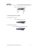
Страница 31: ...install the switch Install the switch to a workbench Install the switch to a 19 inch cabinet 3 3 1 Install the switch to a workbench If you don t want to install the switch to a 19 inch cabinet you can install it on a clearness work bench This kind of installation would be easier You should make sure the following preparations before starting installation The rack is sturdy and securely grounded T...

Страница 32: ...h Technologies Co Ltd 3 3 Figure 3 2 Install the switch to a workbench 3 3 2 Install the switch to a cabinet 3 3 2 1 Mounting ears to your switch Figure 3 3 Mounting ears to your switch 3 3 2 2 Install the switch to a cabinet Figure 3 4 Install the switch to a cabinet Omit cabinet ...

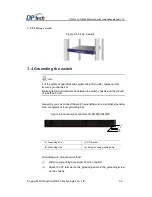
Страница 33: ...ti interference between the switch chassis and the ground is less than 5 ohm Generally you can connect the switch grounding wire to a cabinet grounding strip or equipment room grounding bar Figure 3 6 Grounding connectors of LSW6600 24XGS 1 2 3 4 1 Grounding hole 2 OT terminal 3 Grounding wire 4 Screw on the grounding hole Grounding wire connecting method 1 Dismount grounding hole screw from the c...

Страница 34: ...ch by hexagonal screw You can ground the wire on the floor if you don t have ground row Figure 3 7 Diagram of the grounding wire 1 Hexagonal screw 2 Grounding cable 3 Metal wire of the ground cable which stripped insulation rubber 4 Grounding pole 5 Grounding row 3 5 Connecting interface cable 3 5 1 Connecting configuration port cable The LSW6600 provides an RS 232 asynchronous serial console port...

Страница 35: ... 5 categories twisted pair cable You should be recommended to use shielding twisted pair cable to ensure electromagnetic compatibility The switch doesn t provide any twisted pair cable Prepare it yourself Connect network management port to the terminal computer netword card you must use crossover twisted pair cable 3 5 3 Connecting service port Shielding twisted pair cable ensure electromagnetic c...

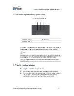
Страница 36: ...d connect your switch to the ground and well connect ground and wiring the cables separately will benefit for the anti interference so that it can ensure the device working normally Verify the voltage value and pin before you connect power on the switch avoid mistake 3 7 Verify the Installation The ground wire is securely connected Both of the console cable and power cord are correctly connected A...

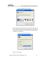
Страница 37: ...the console port on the switch and connect the DB 9 female connector of the console cable to the serial port on the PC that is used for configuring the switch as shown in Figure 4 1 Figure 4 1 Configuring the switch at the initial boot 4 1 1 2 Setting Terminal Parameters You should run HyperTerminal program on the terminal PC when you can configure the terminal PC Follow these steps to set termina...

Страница 38: ...p a new connection On the connection description window you enter a name and click OK as shown in Figure 4 3 displays Then select the serial port to be used from the Connect Using drop down list The serial port must be the same port connected by the console cable Figure 4 3 Setting the connection port Select the Connect using ...

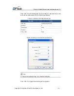
Страница 39: ...d you can set serial port parameters Set the following parameters Table 4 1 Attributes of configure serial port Properties Value Baud rate 9600 bps the default Data bits 8 Parity check None Stop bits 1 Flow control None Figure 4 4 Setting communications parameters To restore the default settings click Restore Defaults Click OK The HyperTerminal dialogue box appears ...

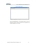
Страница 40: ... 3 Copyright Hangzhou DPtech Technologies Co Ltd 4 4 Figure 4 5 Hyper Terminal Select File Properties Settings In the Properties dialog box select the Settings tab as shown in Figure 4 6 Select VT100 or Auto detect in the Emulation dropdown menu Click OK ...

Страница 41: ...Before powering up the switch check that Both the power cord and the grounding wire are correctly connected Proper power supply is used The console terminal has been started and the related parameters have been set on it Before powering up the switch please verify the power switch position of the switch When danger happens you can power off the switch 4 1 2 2 Powering up the Switch Power up the sw...

Страница 42: ... can view the initial information on terminal PC when you start the device After that after self inspection press Enter key and configure if DPtech displayed 4 1 3 Starting Procedure Powering on your device PC HyperTerminal displays the device self inspection information Then type in the system password and enter the prompt interface There may some differences devices HyperTerminal displayed Use t...

Страница 43: ...plat will boot in 0 Loading main file vmlinux Loading failed don t set main file Loading backup file backup bin error in boot conplat system will back to extend menu please enter the password Password Here the default password is DPTECH 4 2 Default Login Method for Web LSW6600 Series product allow administrator to login through web management interface The default IP address is 192 168 0 1 Adminis...

Страница 44: ...oth of default username and password are admin_default click Login button to enter the Web management interface Figure 4 7 Web management interface We do not suggest you that use both of the http and https protocol to login on the same PC We recommended you that you should modify the default password after first login ...

Страница 45: ...Examine the power plug connection 2 Verity whether the power switch is turned on 3 Verify that the equipment room power switch is turned on 4 Verify the power cord is correct 5 Verify the power voltage is in accordance with device requirement Please do not plug out power cord if the device is still running If you execute the above verification the power LED is still off please contact sales agent ...

Страница 46: ...ort of the device 3 The properties of the terminal are incorrect You must configure the console terminal as follows set Bits per second to 9600 Data bits to 8 Parity to None Stop bits to 1 Flow control to None and Terminal Emulation to VT100 5 2 2 Garbled terminal display Fault phenomenon If terminal display is garbled after you power on the device Troubleshooting Please verify the HyperTerminal p...

Отзывы: