31 / 96
For DPV 25, DPV 40, DPV 60, DPV 85 and DPV 125:
ü
The pressure booster system’s packaging has been removed.
ü
A suitable place of installation has been selected that meets the requirements.
ü
Sufficient clearance in all directions is provided for servicing work.
1. Mark out the anchoring holes on the floor as shown in the outline drawing.
2. Drill the holes (maximum diameter: 12 mm).
3. Insert plug fixings of appropriate size.
4. Place the pressure booster system in its correct installation position.
5. Use suitable bolts to firmly anchor the pressure booster system.
For DPV 2, DPV 4, DPV 6, DPV 10 and DPV 15:
ü
The pressure booster system’s packaging has been removed.
ü
A suitable place of installation has been selected that meets the requirements.
ü
Sufficient clearance in all directions is provided for servicing work.
1. Place the pressure booster system in its correct installation position.
5.3 Mounting the accumulator
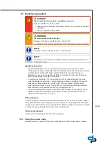
CAUTION
Dirt in the pressure booster system
Damage to the pump sets!
Ø
Clean the accumulator before filling it.
ü
The original operating manual of the pressure booster system is on hand.
1. Mechanically and electrically connect the accumulator in accordance with the original
operating manual supplied.
5.4 Connecting the piping
CAUTION
Air pockets in suction line
Pressure booster system cannot prime!
Ø
Lay the pipe with a continuously rising slope.
1952:116
1
Fig. 13:
Correct piping connection
1
Suction lift operation
1. Mechanically support the suction head line on site to provide for absorption of
mechanical forces.
2. Install the piping without transmitting any stresses and strains.
3. Connect the piping to the distribution lines on the inlet side and discharge side.
Содержание Hydro-Unit Utility Line F
Страница 29: ...29 96 1 2 Fig 12 PE connection 1 Earthing terminal 2 Location of power connection ...
Страница 58: ...58 96 ...
Страница 92: ...92 96 T Tank 79 Timers 73 W Warnings 9 Warranty claims 7 ...
Страница 93: ......
Страница 94: ......
Страница 95: ......


