background image

6

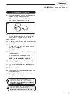
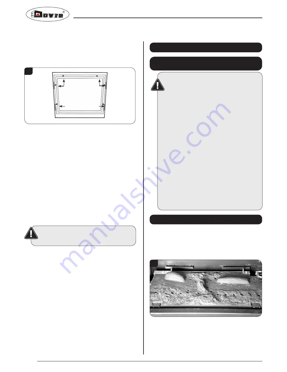
5.5  Remove the glass frame by undoing the fixing screws and 

lifting clear, see Diagram 4. Take care to support the glass 

window panel when removing the screws. 

5.6  Place carefully to one side.

4

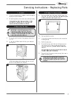
5.7  Lift out the log guard, see Diagram 11. 

5.8  Carefully remove the ceramic fuel bed components and set 

aside. Protect the floor coverings and follow the advice 

given in Section 6. 

5.9  The logs do not require cleaning. Do not use a vacuum 

cleaner or brush to clean the coals, any large pieces of 

debris can be removed by hand.

5.10  Ensure any debris is removed from the burner ports.

5.11  Replace the ceramics, see Section 6.

5.12  Ensure that the rope seal on the back of the glass frame is 

intact and replace the screws working from the top down. 

Tighten the screws evenly DO NOT OVER  TIGHTEN, see 

Diagram 4.

5.13  Replace ALL of the securing screws ensuring that a screw is 

present in all fixing slots.

UNDER NO CIRCUMSTANCES SHOULD THE 

APPLIANCE BE USED IF ANY OF THE FRAME 

RETAINING SCREWS ARE LOOSE OR MISSING.

5.14  With the top still supported or removed refit front by locating 

in grooves and lowering into place, see Diagram 3.

5.15  Replace top, see Diagram 2.


NEVER OPERATE THE APPLIANCE WHEN THE GLASS 

FRAME IS REMOVED, OR THE GLASS IS BROKEN.

5.16  Use a damp cloth to clean the outer casing of the appliance.

User Instructions

6. Arrangement of Fuel Bed

Advice on handling and disposal 

of fire ceramics

The fuel effect of the log version of this 

appliance is made from Refractory Ceramic 

Fibre (RCF), a material which is commonly used 

for this application.

Protective clothing is not required when 

handling these articles, but we recommend you 

follow normal hygiene rules of not smoking, 

eating or drinking in the work area and always 

wash your hands before eating or drinking.

To ensure that the release of RCF fibres are kept 

to a minimum, during installation and servicing 

a HEPA filtered vacuum is recommended to 

remove any dust accumulated in and around the 

appliance before and after working on it. When 

servicing the appliance it is recommended that 

the replaced items are not broken up, but are 

sealed within heavy duty polythene bags and 

labelled as RCF waste.

RCF waste is classed as stable, non-reactive 

hazardous waste and may be disposed of at a 

licensed landfill site.

Excessive exposure to these materials may 

cause temporary irritation to eyes, skin and 

respiratory tract; wash hands thoroughly after 

handling the material.

7. Log Layout


LOGS MUST BE POSITIONED ACCORDING TO THE 

FOLLOWING INSTRUCTIONS TO GIVE THE CORRECT 

FLAME EFFECT

7.1  Ensure the burner tray is clean and free from any debris, 

see Diagram 5.

5


The three logs that make up the fuel bed are visually distinct 

and fit into specific parts on the burner tray.


Содержание 280

Страница 1: ...lass panel scratches scores cracks or other surface defects the glass panel must be replaced and the appliance must not be used until a replacement is installed Under no circumstances should the appliance be used if any damage is observed the glass panel is removed or broken It is essential that ALL of the screws that retain the glass frame are replaced and tightened correctly Under no circumstanc...

Страница 2: ...s 11 Installation 13 Commissioning 18 Servicing Requirements 19 Fault Finding 19 How to replace parts 21 Basic spare parts list 26 Service Records 27 Covering the following models Contents Model NATURAL GAS LPG Black DV541 010 DV541 409 Ivory DV541 042 DV541 440 Black Enamel DV541 093 DV541 456 Majolica Brown DV541 116 DV541 475 ...

Страница 3: ...low Test N A 3 Spillage Test N A GAS CHECK 1 Gas soundness let by test 2 Standing gas pressure mb 3 Appliance working pressure on High Setting NB All other gas appliances must be operating on full mb 4 Gas rate m3 h 5 Does Ventilation meet appliance requirements N A SAFETY CHECK 1 Glass checked to ensure no damage scratches scores or cracks 2 Glass frame secured correctly and all screws replaced R...

Страница 4: ...hecklist on Page 3 1 3 Do not place curtains above the appliance You must have 300mm 1 clearance between the appliance and any curtains at either side 1 4 No furnishings or other objects should be placed within 1 metre of the front of the appliance 1 5 If any cracks appear in the glass panel do not use the appliance until the panel has been replaced 1 6 If for any reason the flue has to be removed...

Страница 5: ...e included with the kit Standard Remote Control PART NUMBER 8455 4 3 This remote control can control the gas appliance after the pilot has been lit It can turn the main burner on and regulate it from low through to high and back again It can turn the main burner off leaving the pilot burning Thermostatic and Timer Remote Control PART NUMBER 8456 4 4 This remote control can control the gas applianc...

Страница 6: ... clean the outer casing of the appliance User Instructions 6 Arrangement of Fuel Bed Advice on handling and disposal of fire ceramics The fuel effect of the log version of this appliance is made from Refractory Ceramic Fibre RCF a material which is commonly used for this application Protective clothing is not required when handling these articles but we recommend you follow normal hygiene rules of...

Страница 7: ... raised molding and the right hand side liner Log 3 8 7 5 Once the logs are in there are two embers which can be loosely placed at the front of the fuel bed and cover the tabs securing the burner tray see Diagram 9 Embers 9 7 6 Use some of the Embaglow provided and cover the ports in the burner tray with a liberal amount of fibres see Diagram 10 It is essential to cover the port in the middle of t...

Страница 8: ...SAYS IT IS SAFE TO DO SO 9 Flame Failure Device 9 1 This is a safety feature incorporated on this appliance which automatically switches off the gas supply if the pilot goes out and fails to heat the thermocouple 10 Running In 10 1 During initial use of a new Dovre appliance a strong odour will be encountered as various surface coatings become hot for the first time Although these odours are harml...

Страница 9: ... 20mbar 6mm x 6mm 260 0 433 4 55 2 5 GB IE I3P Propane G31 37mbar 1 x 14mm x 15mm 102 0 164 4 35 2 5 GB IE Efficiency Class 2 75 NOx Class 4 Flue Outlet Size 127mm 5 ø Gas Inlet Connection Size 8mm ø Minimum flue specification T260 N2 O D 1 Maximum flue temperature 220 C Model NATURAL GAS LPG Black DV541 010 DV541 409 Ivory DV541 042 DV541 440 Black Enamel DV541 093 DV541 456 Majolica Brown DV541 ...

Страница 10: ... the translated instructions and in some cases the appliance will require modification Contact Dovre for further information PACKING CHECKLIST Qty Description Fixing Kit containing 1 x Appliance 1 x Flue Infill Plate 1 x Log Set 1 x Packet of Embaglow 1 x Instruction Manual Installation Instructions Technical Specification 381 138 494 560 391 351 30 30 ...

Страница 11: ...nt the Dovre 280 Please contact your Dovre retailer for further information 3 Gas Supply THIS APPLIANCE IS INTENDED FOR USE ON A GAS INSTALLATION WITH A GOVERNED METER 3 1 Before installation ensure that the local distribution conditions identification of the type of gas and pressure and the adjustment of the appliance are compatible 3 2 Ensure the gas supply delivers the required amount of gas an...

Страница 12: ...ls If the appliance is intended to be installed into a non combustible opening the clearance to the sides and above the appliance can be reduced However it is recommended that the specified clearances are maintained irrespective of the materials used in the construction of the opening to allow adequate air flow and access to controls The clearance at the rear of the appliance must always be a mini...

Страница 13: ...ccording to local and national codes of practice Failure to install the appliance correctly could lead to prosecution Read these instructions before installing and using this appliance 1 2 These instructions must be left intact with the user 1 3 Do not attempt to burn rubbish on this appliance 1 4 Keep all plastic bags away from young children 1 5 Do not place any object on or near to the applianc...

Страница 14: ...t 4 Gas Soundness Pressure Check 4 1 Connect a suitable pressure gauge to the test point located on the inlet fitting and turn the gas supply on Light the appliance and check all gas joints for possible leaks Turn the appliance to maximum and check that the supply pressure is as stated on the databadge Turn the gas off and replace the test point screw turn the gas on and check the test point for l...

Страница 15: ...aste is classed as stable non reactive hazardous waste and may be disposed of at a licensed landfill site Excessive exposure to these materials may cause temporary irritation to eyes skin and respiratory tract wash hands thoroughly after handling the material 7 Log Layout LOGS MUST BE POSITIONED ACCORDING TO THE FOLLOWING INSTRUCTIONS TO GIVE THE CORRECT FLAME EFFECT 7 1 Ensure the burner tray is ...

Страница 16: ...ition see Diagram 11 11 8 Completion of Assembly 8 1 Use a ceramic glass product generally sold for cleaning ceramic hobs to clean the glass front 8 2 Ensure that the rope seal on the back of the glass frame is intact and replace the screws working from the top down Tighten the screws evenly DO NOT OVER TIGHTEN see Diagram 12 NEVER OPERATE THE APPLIANCE WHEN THE GLASS FRAME IS REMOVED OR THE GLASS...

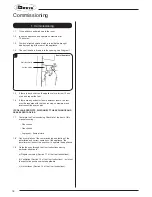
Страница 17: ...lot is lit 9 5 Keep the knob depressed for 10 seconds before releasing The pilot remains lit Repeat the above steps if the pilot does not stay lit NOTE If the pilot goes out the Interlock system prevents you lighting again for a short period 9 6 If after repeating the above steps the pilot does not light contact your Retailer or Installer 9 7 Turn the right hand knob to the left to main burner set...

Страница 18: ... running on maximum and interconnecting doors open IF SPILLAGE PERSISTS DISCONNECT THE APPLIANCE AND SEEK EXPERT ADVICE 1 7 Complete the Commissioning Checklist at the front of this manual covering Flue checks Gas checks Log layout flame picture 1 8 Upon completion of the commissioning and testing of the installation and correct operation of the appliance the installer must instruct the user how t...

Страница 19: ... away lint or fluff from the pilot Clean away lint or fluff from under the burner Check the spark gap on the pilot is correct see Diagram 1 Ensure that the glass frame is secured correctly and that all retaining screws are in place 1 3 Correct any faults found during the initial test 1 4 Re commission the appliance in accordance with Commissioning Procedures 1 5 Advise the customer of any remedial...

Страница 20: ...onds turn off time interval until mag unit shuts with a click Is this greater than 7 seconds Tighten the connection and retry No No No No No No Yes SYSTEM OK Yes Yes Yes Yes No Yes Yes No Light the pilot and keep the control knob pushed in at least 10 seconds before releasing NO SPARK Ensure there is no debris around the pilot assembly e g soot etc which could short the spark clean the area Consul...

Страница 21: ...ent in all fixing slots UNDER NO CIRCUMSTANCES SHOULD THE APPLIANCE BE USED IF ANY OF THE GLASS FRAME RETAINING SCREWS ARE LOOSE OR MISSING 1 General 1 1 All main components can be replaced without removing the appliance from its installation 1 2 Ensure the appliance and surrounds are cool before servicing IT IS ESSENTIAL THAT THE GAS SUPPLY TO THE APPLIANCE IS TURNED OFF AT THE ISOLATION DEVICE B...

Страница 22: ...ards the centre of the firebox before lifting up and pulling out through the front of the firebox see Diagram 5 5 4 5 To remove the Right Hand liner first tilt inwards towards the centre of the firebox before lifting up and pulling out through the front of the firebox see Diagram 5 The two side liners also support the raised rear liner Taking out the side liners will allow the rear liner to drop d...

Страница 23: ...er bracket 6b Pilot injector 6c Electrode 6d Thermocouple 6e Gasket 6 2 Turn the gas supply off at the isolation device remove the door and place to one side carefully remove the ceramic fuel bed components 6a Pilot Burner Bracket 6 3 Remove the two fixing screws from the pilot bracket see Diagram 11 Gently draw the assemble away from the firebox to give access to the nuts and ignition lead NOTE T...

Страница 24: ...ssembly 15 16 7 4 Disconnect the other end of the ignition lead from the valve body noting the route of the ignition lead 7 5 Replace with a new ignition lead following the same route as the old one Replace the valve cover and the pilot assembly 7 6 Check operation of the new ignition lead 8 Piezo 8 1 The piezo assembly used on this appliance is not serviceable and is unlikely to fail 8 2 If a new...

Страница 25: ...ector 11 1 To remove the main injector turn off the gas supply at the isolation device 11 2 Remove the main burner see Section 5 11 3 Undo the compression nuts from the feed pipe and the gas valve under the appliance 11 4 Working from inside the firebox remove the lock nut from the injector see Diagram 19 19 11 5 Extract the injector with the feed pipe from beneath the appliance 11 6 Holding the i...

Страница 26: ...ng Between Gas Types In order to change between gas types it will be necessary to change the following items Pilot Injector Control Valve Injector Aeration Plate if required Data Badge A kit of parts is available for this always quote the Model number and Serial number when ordering any spare parts NOTE THE CONTROL VALVE IS FACTORY PRESET FOR THE CORRECT GAS TYPE AND MODEL A NEW UNIT WILL NEED TO ...

Страница 27: ...9TH SERVICE Date of Service Next Service Due Signed Retailer s Stamp Gas Safe Registration Number 2ND SERVICE Date of Service Next Service Due Signed Retailer s Stamp Gas Safe Registration Number 4TH SERVICE Date of Service Next Service Due Signed Retailer s Stamp Gas Safe Registration Number 6TH SERVICE Date of Service Next Service Due Signed Retailer s Stamp Gas Safe Registration Number 8TH SERV...

Страница 28: ...E O E ...

Отзывы: