Dover PSG Wilden PX220 Скачать руководство пользователя страница 22

WILDEN PUMP & ENGINEERING, LLC 

20 

WIL-11610-E-02

To o l s   R e q u i r e d :

•   13 mm (1/2") Box 

Wrench

•   2 – 25 mm (1") Sockets 

or Adjustable Wrench

•   Adjustable  Wrench
•   Vise equipped with 

soft jaws (such as 
plywood, plastic 
or other suitable 
material)

CAUTION:  Before any maintenance or repair is attempted, the compressed air line 
to the pump should be disconnected and all air pressure allowed to bleed from the 
pump. Disconnect all intake, discharge and air lines. Drain the pump by turning it 
upside down and allowing any fluid to flow into a suitable container. Be aware of 
any hazardous effects of contact with your process fluid.
NOTE: The model used for these instructions incorporates rubber diaphragms and 
balls. Models with PTFE diaphragms and balls are the same except where noted. 

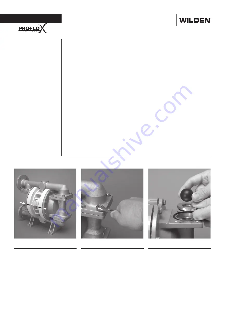
Step 1

Please note alignment marks on 
center section.  Use to properly align 
liquid chamber to center section.

Step 2 

Using a 13 mm (1/2") wrench, 
loosen the discharge manifold from 
the liquid chambers.

Step 3

Remove the discharge manifold to 
expose the valve balls, valve seats 
and valve seat O-rings.

S e c t i o n   7

P U M P   D I S A S S E M B L Y

Содержание PSG Wilden PX220

Страница 1: ...PX220 PX230 Metal Pump EOM Engineering Operation Maintenance wildenpump com Where Innovation Flows ...

Страница 2: ...etal Rubber Fitted 12 PX220 PX230 MetalTpe Fitted 13 PX220 PX230 Metal Reduced Stroke PTFE Fitted 14 PX220 PX230 Metal Full Stroke PTFE Fitted 15 Suction Lift Curves 16 SECTION 6 SUGGESTED INSTALLATION OPERATION TROUBLESHOOTING 17 SECTION 7 DISASSEMBLY REASSEMBLY 20 Grounding Strap for CSA Pumps 22 Air Valve Disassembly 23 Reassembly Hints Tips 26 SECTION 8 EXPLODED VIEW PARTS LISTING PX220 PX230 ...

Страница 3: ...g natural gas supply pressure CAUTION The process fluid and cleaning fluids must be chemically compatible with all wetted pump components Consult the Chemical Resistance Guide CAUTION Do not exceed 82 C 180 F air inlet temperature for Pro Flo X models CAUTION Pumps should be thoroughly flushed before installing into process lines FDA and USDA approved pumps should be cleaned and or sanitized befor...

Страница 4: ...mm 3 4 NPT center ported discharge manifold Pro Flo Drop in 0698 19 mm 3 4 BSPT center ported discharge manifold Pro Flo Drop in 0735 19 mm 3 4 NPT center ported discharge manifold Turbo Flo Drop in Submersible Center Section 0736 19 mm 3 4 BSPT center ported discharge manifold Turbo Flo Drop in Submersible Center Section 0737 19 mm 3 4 NPT center ported discharge manifold Pro Flo Drop in Submersi...

Страница 5: ... fluid to flow through the pump discharge The movement of diaphragm A toward the center of the pump creates a vacuum within liquid chamber A Atmos pheric pressure forces fluid into the inlet manifold of the pump The inlet valve ball is forced off its seat allowing the fluid being pumped to fill the liquid chamber FIGURE 3 At completion of the stroke the air valve again redirects air to the back si...

Страница 6: ...NDARD inch A 361 14 2 B 36 1 4 C 163 6 4 D 254 10 0 E 287 11 3 F 56 2 2 G 384 15 1 H 71 2 8 J 140 5 5 K 155 6 1 L 206 8 1 M 173 6 8 N 104 4 1 P 127 5 0 R 10 0 4 LW0448 REV A DIMENSIONS ITEM METRIC mm STANDARD inch A 422 16 6 B 36 1 4 C 163 6 4 D 254 10 0 E 287 11 3 F 33 1 3 G 384 15 1 H 71 2 8 J 140 5 5 K 155 6 1 L 206 8 1 M 173 6 8 N 104 4 1 P 127 5 0 R 10 0 4 LW0449 REV A ...

Страница 7: ...SIONS ITEM METRIC mm STANDARD inch A 373 14 7 B 69 2 7 C 195 7 6 D 287 11 3 E 340 13 4 F 343 13 5 G 71 2 8 H 384 15 1 J 71 2 8 K 140 5 5 L 188 7 4 M 206 8 1 N 173 6 8 P 104 4 1 R 127 5 0 S 10 0 4 DIN FLANGE T 85 DIA 3 3 DIA U 115 DIA 4 5 DIA V 14 DIA 0 6 DIA ANSI FLANGE T 79 DIA 3 1 DIA U 109 DIA 4 3 DIA V 14 DIA 0 6 DIA LW0450 REV A ...

Страница 8: ...S e c t i o n 5 B N O T E S ...

Страница 9: ...P X 2 2 0 P X 2 3 0 P E R F O R M A N C E PX220 PX230 M E T A L ...

Страница 10: ...ity that exceeds previous industry standards Pro Flo XTM Operating Principle S e c t i o n 5 B Turning the dial changes the relationship between air inlet and exhaust porting Each dial setting represents an entirely different flow curve Pro Flo X pumps are shipped from the factory on setting 4 which is the highest flow rate setting possible Moving the dial from setting 4 causes a decrease in flow ...

Страница 11: ... this case 9 8 scfm Step 2 Determining flow and air X Factors Locate your discharge pressure 2 8 bar 40 psig on the vertical axis of the EMS curve Figure 2 Follow along the 2 8 bar 40 psig horizontal line until intersecting both flow and air curves for your desired EMS setting in this case set ting 2 Mark the points where the EMS curves intersect the horizontal discharge pressure line After locati...

Страница 12: ...ar 40 psig discharge pressure After locat ing this point on the flow curve draw a verti cal line downward until reaching the bottom scale on the chart and identify the flow rate In our example it is 38 6 lpm 10 2 gpm This is the setting 4 flow rate Observe the loca tion of the performance point relative to air consumption curves and approximate air consumption value In our example setting 4 air co...

Страница 13: ...is different than the flow point plotted in example 2 1 Af ter estimating or interpolating this point on the curve draw a vertical line downward un til reaching the bottom scale on the chart and identify the air X Factor Figure 7 Step 2 Determine air consumption Multiply your setting 4 air consumption 14 scfm value by the air X Factor obtained above 0 40 to deter mine your actual air consumption I...

Страница 14: ... setting NOTE You can interpolate between the setting curves for operation at intermediate EMS settings EXAMPLE A PX220 PX230 metal rubber fitted pump operating at EMS setting 4 achieved a flow rate of 87 lpm 23 gpm using 49 Nm 3 h 29 scfm of air when run at 5 5 bar 80 psig air inlet pressure and 4 1 bar 60 psig discharge pressure see dot on performance curve The end user did not require that much...

Страница 15: ...how to set your EMS see beginning of perfor mance curve section Caution Do not exceed 8 6 bar 125 psig air supply pressure Canadian Standards Association CSA configured pumps should not exceed 6 9 bar 100 psig natural gas supply pressure Please read all cautions and suggested installation sections before operating any Wilden product The Efficiency Management System EMS can be used to optimize the ...

Страница 16: ... setting NOTE You can interpolate between the setting curves for operation at intermediate EMS settings EXAMPLE A PX220 PX230 metal reduced stroke PTFE fitted pump operating at EMS setting 4 achieved a flow rate of 129 lpm 34 gpm using 75 Nm 3 h 44 scfm of air when run at 5 5 bar 80 psig air inlet pressure and 0 7 bar 10 psig discharge pressure see dot on performance curve The end user did not req...

Страница 17: ...e curve to calculate the actual flow and air consumption values for that specific EMS setting NOTE You can interpolate between the setting curves for operation at intermediate EMS settings EXAMPLE A PX220 PX230 metal full stroke PTFE fitted pump operating at EMS setting 4 achieved a flow rate of 95 lpm 25 gpm using 51 Nm 3 h 30 scfm of air when run at 4 1 bar 60 psig air inlet pressure and 2 8 bar...

Страница 18: ...305 m 1 000 above sea level This chart is meant to be a guide only There are many variables that can affect your pump s operating characteristics The number of intake and discharge elbows viscosity of pumping fluid elevation atmospheric pressure and pipe friction loss all affect the amount of suction lift your pump will attain WILDEN PUMP ENGINEERING LLC 16 PX220 PX230 Performance ...

Страница 19: ...e reduced below OSHA specifications using the standard Wilden muffler Other mufflers can be used to further reduce sound levels but they usually reduce pump performance ELEVATION Selecting a site that is well within the pump s dynamic lift capability will assure that loss of prime issues will be eliminated In addition pump efficiency can be adversely affected if proper attention is not given to si...

Страница 20: ...y to the pump therefore stopping output This shut off valve should be located far enough away from the pumping equipment such that it can be reached safely in an emergency situation NEEDLE VALVE AIR SHUT OFF VALVE FOOTPAD COMBINATION FILTER REGULATOR SUCTION MUFFLER FLEXIBLE CONNECTION FLEXIBLE CONNECTION GAUGE OPTIONAL EQUALIZER SURGE DAMPENER OPTIONAL SHUT OFF VALVE DISCHARGE WILDEN PUMP ENGINEE...

Страница 21: ... it possible to identify pumps that are poorly suited to their applications Pump will not run or runs slowly 1 Ensure that the air inlet pressure is at least 0 3 bar 5 psig above startup pressure and that the differential pressure the difference between air inlet and liquid discharge pressures is not less than 0 7 bar 10 psig 2 Check air inlet filter for debris see SUGGESTED INSTALLATION 3 Check f...

Страница 22: ... by turning it upside down and allowing any fluid to flow into a suitable container Be aware of any hazardous effects of contact with your process fluid NOTE The model used for these instructions incorporates rubber diaphragms and balls Models with PTFE diaphragms and balls are the same except where noted Step 1 Please note alignment marks on center section Use to properly align liquid chamber to ...

Страница 23: ... Step 6 Remove the inlet valve balls seats and valve seat O rings from the liquid chamber and inlet manifold inspect for nicks gouges chemical attack or abrasive wear Step 7 Using a 13 mm 1 2 wrench remove the liquid chambers from the center section Step 8 The liquid chamber should be removed to expose the diaphragm and outer piston Rotate center section and remove the opposite liquid chamber Step...

Страница 24: ...OUND ING STRAP FOR CSA PX220 PX230 PUMPS Canadian Standards Association CSA configured pumps must be electrically grounded using the grounding strap provided Figure 1 Improper grounding can cause improper and dangerous operation To properly attach the grounding strap to a CSA configured PX220 PX230 pump identify the designated grounding location on the muffler plate using the provided self tapping...

Страница 25: ...your process fluid The PX220 PX230 metal pumps uses the Pro Flo X air distribution system A 6 mm 1 4 air inlet connects the air supply to the center section Proprietary composite seals reduce the co efficient of friction and allow the pump to run lube free Constructed of polypropylene the Pro Flo air distribution system is designed to perform in on off non freezing non stalling tough duty applicat...

Страница 26: ...ly Step 6 Remove pilot spool sleeve retaining snap ring on both sides of center section with snap ring pliers Step 7 Remove pilot spool sleeve from center section Step 8 With O ring pick gently remove the O ring from the opposite side of the center hole cut on the spool Gently remove the pilot spool from sleeve and inspect for nicks gouges or other signs of wear Replace pilot sleeve assembly or ou...

Страница 27: ...lace S U B M E R S I B L E P R O F L O X Step 2 Next install an optional submersible air valve gasket 02 2621 52 The submersible air valve gasket can be purchased as a spare part or included with the purchase of a new Pro Flo X pump Step 1 Install a 1 4 NPT pipe plug 00 7010 08 or 00 7010 03 into the pilot spool bleed port located at the front of the center section Non Submersible Submersible ...

Страница 28: ...llowing tools can be used to aid in the installation of the new seals Needle Nose Pliers Phillips Screwdriver Electrical Tape Wrap electrical tape around each leg of the needle nose pliers heat shrink tubing may also be used This is done to prevent damaging the inside surface of the new seal With a new seal in hand place the two legs of the needle nose pliers inside the seal ring See Figure A Open...

Страница 29: ...N O T E S ...

Страница 30: ... i n g S e c t i o n 8 E X P L O D E D V I E W P A R T S L I S T I N G PX220 PX230 METAL E X P L O D E D V I E W WILDEN PUMP ENGINEERING LLC 28 WIL 11610 E 02 METAL ADS STAINLESS STEEL FLANGED FULL STROKE PTFE REDUCED STROKE PTFE FULL STROKE IPD LW0451 REV A ...

Страница 31: ... 01 02 5035 02 697 02 5035 03 Discharge Manifold Side Ported 1 BSPT 1 02 5036 01 02 5036 02 698 02 5036 03 Discharge Manifold Center Ported 3 4 NPT 1 02 5035 01 697 02 5035 02 677 02 5035 03 697 Discharge Manifold Center Ported 3 4 BSPT 1 02 5036 01 698 02 5036 02 678 02 5036 03 698 Discharge Manifold Center Ported 1 NPT 1 02 5035 01 677 02 5030 02 02 5035 03 677 Discharge Manifold Center Ported 1...

Страница 32: ...1010 86 N A N A N A N A N A N A N A N A N A FKM 02 1010 53 N A N A N A N A N A 02 1085 53 N A 02 1205 53 02 1372 53 EPDM 02 1010 54 N A N A N A N A 02 1060 54 02 1085 54 N A 02 1205 54 02 1372 54 PTFE N A 02 1040 55 N A N A 02 1010 55 N A 02 1085 55 N A 02 1205 55 70 1280 55 Saniflex 02 1010 56 N A 02 1065 56 02 1031 56 N A 02 1060 56 02 1085 56 N A 02 1205 56 02 1372 56 Wil Flex 02 1010 58 N A N ...

Страница 33: ...N O T E S ...

Страница 34: ...N O T E S ...

Страница 35: ...ms for warranty consideration and must be accompanied by the appropriate MSDS for the product s involved A Return Goods Tag obtained from an authorized Wilden distributor must be included with the items which must be shipped freight prepaid The foregoing warranty is exclusive and in lieu of all other warranties expressed or implied whether written or oral including all implied warranties of mercha...

Страница 36: ...313 5607 P 1 909 422 1730 F 1 909 783 3440 wildenpump com PSG reserves the right to modify the information and illustrations contained in this document without prior notice This is a non contractual document 11 2018 Copyright 2018 PSG ADoverCompany LISTED 79 WIL 11610 E 02 REPLACES WIL 11610 E 01 ...

Отзывы: