


501-K00 Page 5/12
INSTALLATION
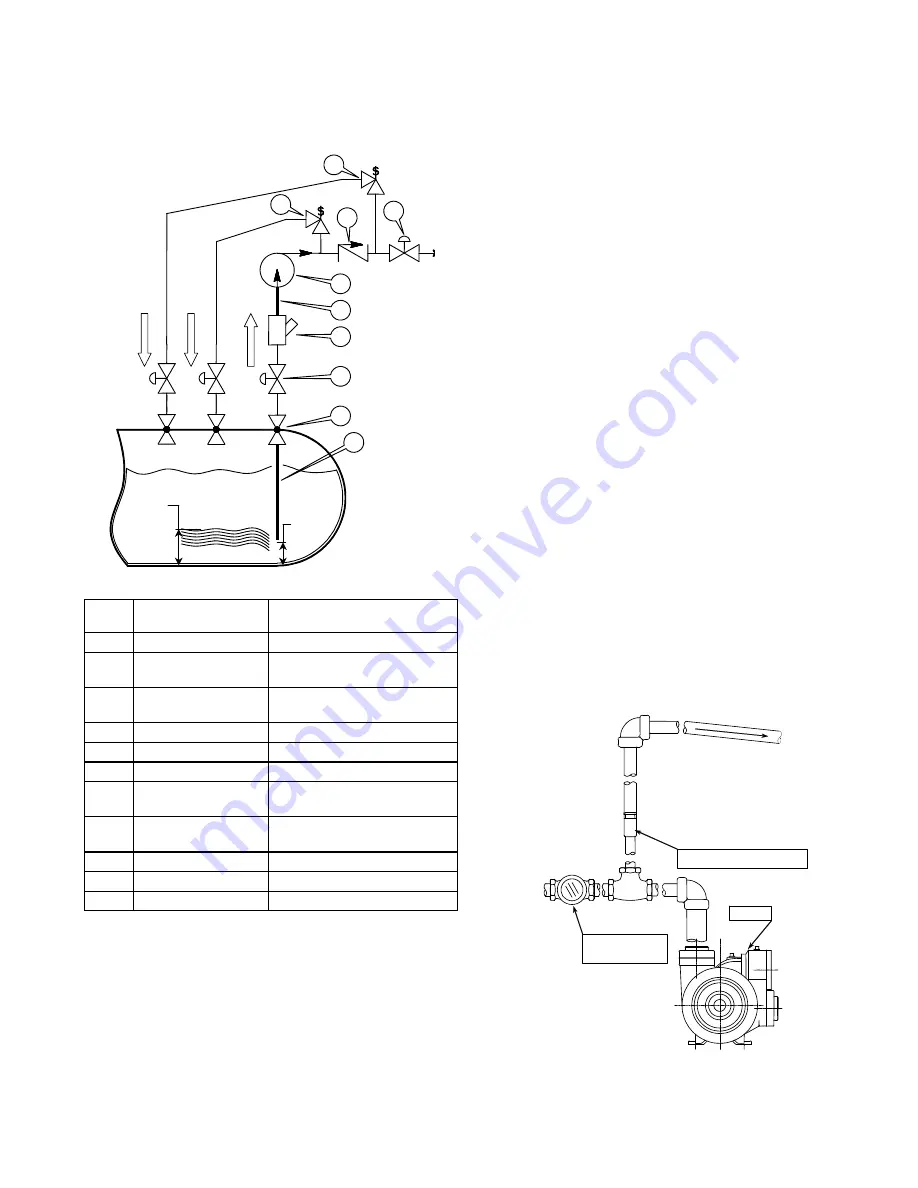
GUIDE TO UNDERGROUND TANK
APPLICATIONS
PUMP
VAPOR
BV
TANK
3 "
15 %
MIN.
LEVEL
3
2
1
4
5
6
7
8
9
10
Fig. 5 – Underground Tank Schematic
No.
Description
LGL150 Series Pumps
1
Dip Tube
2"
2
Excess Flow Valve Fisher F190, Rego A2137A,
or equivalent
3
Control Valve - Full
Flow Ball
2"
4
Strainer (Optional)
2"
5
Inlet Piping
2"
6
Pump Speeds
1150, 1450, & 1750 RPM
7
Back Check Valve Fisher G200-16, Rego A7794
(sight glass) or equivalent
8
Control Valve - Full
Flow Ball
1.5"
9
Bypass Valve
BV1.5"
10
Priming Valve
Fisher F138* or equivalent
11
Minimum Tank Size
2,000 Gal (7570 liters)
* Blackmer PN: 455750
When pumping from an underground tank, the change in
elevation from the fluid level in the tank to the inlet of the
pump will cause significant vaporization of the fluid in the inlet
piping. For this reason alone, it is impossible to prevent
vaporization at the inlet of the pump for an underground tank
installation. However, there are many things that can be
done to minimize these effects. Refer to figure 5. See
Bulletin 500-002 “Underground Tank Application Guide” for
more detailed information.
For an underground tank installation, the piping between the
pump and the tank is filled with vapor when the pump is at
rest. This vapor must be removed before the pump can
prime. Reducing the amount of vapor during startup and
operation will greatly enhance the pump’s performance.
Inlet Piping Length
Keep the inlet piping as short as possible. Install the pump
directly over the tank and as close to the ground as possible.
Minimize the Number of Fittings
Every fitting, valve, and piece of straight piping causes a
pressure drop and adds to the startup vapor volume. Use a
minimum number of fittings on the inlet side of the pump.
Eliminate all possible elbows in the inlet piping by moving the
pump so that they will not be necessary. Size the inlet piping
per the table.
Strainers (4)
Suction strainers should not normally be used on
underground tank installations. The end of the dip tube
should be placed 2 – 3” (5 – 8 cm) above the bottom of the
tank. In applications with known high levels of contaminates,
install a strainer that is one or two sizes larger than the pump.
Vapor Priming Valve (10)
Install a vapor priming (excess flow) valve on the discharge
side of the pump, between the soft seat back check valve and
the pump. Refer to figures 5 and 6. The vapor excess flow
valve provides a path to return the vapors to the tank during
startup. When liquid flow is established, the vapor excess
flow valve will close. When piping the return line from the
vapor excess flow valve to the tank, ensure that there are no
low spots where liquid can collect. Pipe the vapor return line
to the vapor space in the tank, NOT to the liquid space of the
tank or to the inlet of the pump.
Soft Seat Back Check Valve (7)
Install a soft seat back check valve on the discharge side of
the pump as close as possible. A swing valve is preferred.
Refer to figure 6.
BACKCHECK
VALVE
PUMP
VAPOR PRIMING VALVE
BACK TO
VAPOR
SPACE OF TANK.
SLOPE HORIZONTAL PIPING
DOWNWARD TOWARD TANK.
Fig. 6 – Vapor Priming Valve and Back Check Valve