


Page
|
2
REV#0002A
TJ1107XEDR
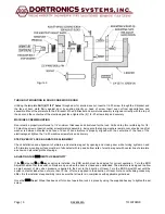
STEP 2) MAKE ELECTRICAL CONNECTIONS
.
The TJ1107xEDR electro-magnetic lock should be connected to a Class 2 power supply
. Leads are connected in series
for 24 volt operation (as shipped from the factory) or connected in parallel for 12 volt operation.
For 12 volt operation
, cut
the gray wire to make 2 equal lengths, strip back the insulation 3/8” on each lead and connect each gray wire end to the
closer blue wire end – see Figure 2 below.
Note: For 12 VDC (parallel coils) the gray wire must be connected to the
adjacent blue wire or the magnetic bond will be significantly reduced.
Connect the 20 AWG Normally Closed white and green wires to the lock controller.
Connect the black 22 AWG wire to the common connection of the access control input for monitoring door status (DPS).
Then connect either the
white
wire (for systems requiring normally closed contacts
with door in closed position
) or the
red
wire (for systems requiring normally open contacts
with door in closed position
). Refer to the device manual for details.
Typically, Dortronics access control systems look for closed contacts to indicate that the door is secure (closed).
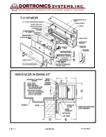
STEP 3) INSTALLING THE ARMATURE MOUNT Z-BRACKET
The armature is carried by the Z-Bracket that mounts at the top edge of the door. The centerline of the armature should line
up with the centerline of the face of the electromagnet. Use the supplied template to mark the door for drilling. Depending on
the door structure and material, use either sex nuts and 1/4-20 machine screws or drill and tap the door for 1/4-20 machine
screws.
THRU BOLT MOUNTING IN HOLLOW METAL DOOR
Utilizing the template
Drill (4) 11/32”
holes
through door. Enlarge hole in outside face only to
1/2”
for knurled sex nut. Insert
a 1/4-20 screw through the Z-bracket and the face of door. Hold firmly against door by pushing directly on head of screw.
Insert sex nut from opposite face and assemble. Mount the armature to the Z-Bracket. When Z-Bracket and armature
assembly is aligned correctly with the top of the door and the centerline of the electromagnet face, tighten the (4) 1/4 -20
screws fully and securely.
Hollow metal doors with insufficient material thickness (1/4” is the minimum recommended thickness) to withstand the holding
force of the magnetic pull, or that might deform as the mounting hardware is tightened must be reinforced.
Figure
2
Содержание TJ1107xEDR TOP JAMB Series
Страница 4: ...Page 4 REV 0002A TJ1107XEDR Figure 4...
Страница 5: ...Page 5 REV 0002A TJ1107XEDR...
Страница 6: ...Page 6 REV 0002A TJ1107XEDR...


