1
5
2 - 4
3
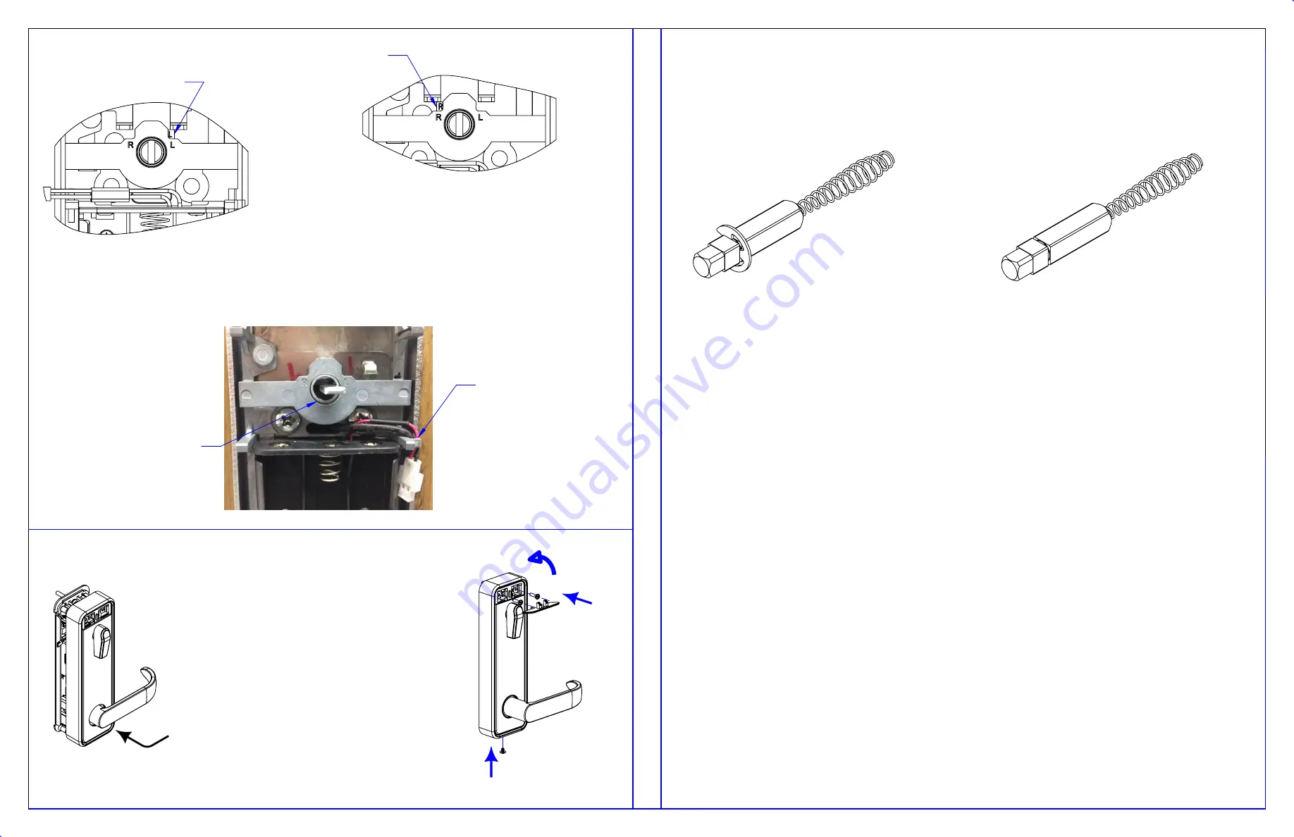
SPINDLE & RETAINING ASSEMBLY FOR INSIDE TRIM
FOR A LEFT HAND SIDE LOCK, IT SHALL BE POSSIBLE TO ALIGN CAM SLOT
VERTICALY AS SHOWN. IF NOT, INSIDE TRIM CHASSIS AND SLIDER ASSEMBLY
DO NOT HAVE THE PROPER HANDING AND MUST BE REVERSE.
CAM HANDING INDICATOR
FOR A RIGHT HAND SIDE LOCK, IT SHALL BE POSSIBLE TO ALIGN CAM SLOT
VERTICALY AS SHOWN. IF NOT, INSIDE TRIM CHASSIS AND SLIDER ASSEMBLY
DO NOT HAVE THE PROPER HANDING AND MUST BE REVERSE.
CAM HANDING INDICATOR
SPINDLE ASSEMBLY FOR LEVER & ROSE
PK3710 - Rev 2
11. INSTALL INSIDE COVER
10. INSTALL INSIDE TRIM ASSEMBLY
This device complies with Industry Canada license-exempt RSS standard(s). Operation is subject to the following two
conditions: (1) this device may not cause interference, and (2) this device must accept any interference, including
interference that may cause undesired operation of the device.
Le présent appareil est conforme aux CNR d’Industrie Canada applicables aux appareils radio exempts de licence.
L’exploitation est autorisée aux deux conditions suivantes : (1) l’appareil ne doit pas produire de brouillage, et (2)
l’utilisateur de l’appareil doit accepter tout brouillage radioélectrique subi, même si le brouillage est susceptible d’en
compromettre le fonctionnement.”
Note: This equipment has been tested and found to comply with the limits for a Class B digital device, pursuant to part 15
of the FCC Rules. These limits are designed to provide reasonable protection against harmful interference in a residential
installation. This equipment generates, uses and can radiate radio frequency energy and, if not installed and used in
accordance with the instructions, may cause harmful interference to radio communications. However, there is no
guarantee that interference will not occur in a particular installation. If this equipment does cause harmful
interference to radio or television reception, which can be determined by turning the equipment off and on, the user is
encouraged to try to correct the interference by one or more of the following measures:
• Reorient or relocate the receiving antenna.
• Increase the separation between the equipment and receiver.
• Connect the equipment into an outlet on a circuit different from that to which the receiver is connected.
• Consult the dealer or an experienced radio/TV technician for help.”
Changes or modifications not expressly approved by the party responsible for compliance could void the user’s authority
to operate the equipment
This device complies with part 15 of the FCC Rules. Operation is subject to the following two conditions: (1) This device
may not cause harmful
interference, and (2) this device must accept any interference received, including interference that may cause undesired
operation.
IF SPINDLE IS DISCONNECTED FROM LEVER, RE-INSERT SPRING IN LEVER AS FOLLOW:
PUSH THE SPRING LIGHTLY INSIDE LEVER HOLE AND GENTLY TWIST THE SPINDLE AND SPRING ASSEMBLY 2 OR 3 TURNS
COUNTERCLOWISE
THEN PRESS THE SPINDLE ALL THE WAY IN.
AFTER CONNECTING THE CABLES,
ROUTE THE CABLES AROUND THE
CLIPS
SLIDE THE COVER OVER THE LEVER WITHOUT SCRATCHING
1.
THE LEVER.
LIGHTLY SCREW IN THE TWO UPPER SCREWS.
2.
INSTALL THE LOWER SCREW.
3.
TIGHTEN THE UPPER SCREWS IN PLACE.
4.
SNAP IN THE COVER.
5.
ROTATE THE CAM SO THAT THE INNER
SLOT IS HORIZONTAL THEN PLACE THE
INSIDE TRIM INTO POSITION


