

(P/N) 3118.0210 Rev C 06/18 • © copyright 2010-2018
dormakaba USA Inc.
Page 3 of 4
Part II: Install Lock Case Assembly
WARNING: Do not take the lock case assembly apart. The lock will not operate if the back cover
has been removed. There are no field serviceable parts inside lock case. This action will void the
lock warranty.
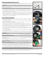
1. Ensure that the cable lays in the cable channel as you mount the lock case assembly to the
inside of the container door using the three 1/4-20 (or M6-1) screws (Torque 25-30 lbs., 2.8-3.4
N-M), allowing 1/20" (1.27mm) clearance between the lock bolt and the container locking bar.
(See Figure 2 for proper clearances and positioning when installing a swing bolt.)
NOTE:
The lock case assembly can be mounted in bolt up position (Figure 11) or bolt down
position for all mounting locations. The movement of the boltworks must however contact
the bolt on the flat edge, not on the rounded side of the bolt. It is recommended that you use
Loctite® 262 (Red) on the lock case mounting screws.
2. Test the operation of the lock again. If the lock does not operate properly, refer to the
following instructions to “Uninstall Keypad Assembly”.
3. If your lock includes the Battery Assist option, you should now mount the battery clip inside
the door near the lock and install a fresh 9 Volt Alkaline battery.
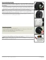
NOTE:
To remove any excess cable or if you choose not to use the Battery Assist option, wrap
and tie the battery assist cable. (Figure 13.)
Figure 9
Figure 10
Figure 11
Figure 13
Figure 12
Uninstall Keypad Assembly
1. Remove the decal from the keypad assembly.
2. Insert a flat head screwdriver into the slot in the upper left hand corner of the keypad to
release one of the two keypad catches. (Figure 12.)
3. Carefully pull the keypad assembly out from the dial assembly.
4. Check for pinched or detached cables.


