


EM 6900 AM B
—
3
DORMA
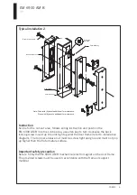
Typical installation 2
Instruction
Important safety precaution
Scribe for the cut-out area, follows wiring instruction and position the
EM 6900 AM B into the scribe area, use allen key to turn clockwise the back
locking screw mount up the unit tight against the door frame (refer to installation
diagram). The top piece sleeve nut must be screw tight and glue and must not pop
up higher than the flat armature surface.
Secure firmly the EM 6900 AM B mechanical electro magnet on the door frame.
The provided screws must be used in accordance with the frame or support
material.
Note: Sizes with (A) denote additional 1mm clearance.
Sizes with (B) denote additional 2mm clearance.
2mm allen key
2mm allen key
Door frame
Bearing sleeve nut
Back locking screw
Drill holes,
4 places
4.2
9.5
21.5
12
35.5
36.5 (A)
7.75
15.5
166
176 (B)
186
5.5


