background image


Doosan  Robotics  Installation  Manual  v2.1


188 

1. 

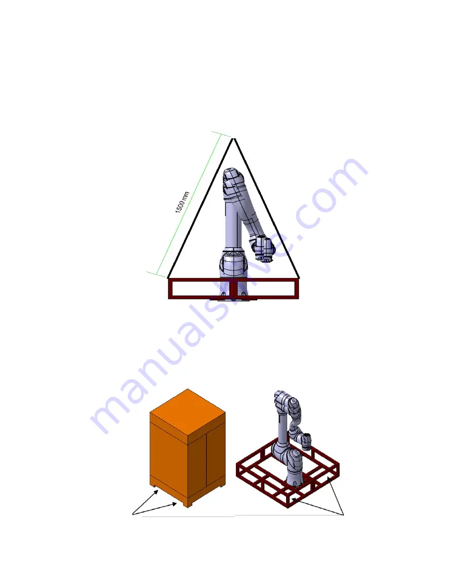
When  Using  Cranes 


The  weight  of  the 

robot 

is  approximately  70  kg.  Use  wire  ropes  capable  of  handling  the  w

eight  of  the 

robot


The  length  of  the  wire  ropes  must  be  at  least  1500  mm,  and  it  is  recommended  to  support
  4  points  of  the 

robot 

at  least. 


2. 

When  Using  Forklifts 


If  the 

robot 

needs  to  be  relocated  in  its  packaged  state,  lift  the  bottom  of  the  package  usin

g  a  forklift. 


When  installation,  relocate  the 

robot 

using  the  lower  packaging  materials  while  taking  cautio

n  to  avoid  damage  to  the 

robot

.   


Insertion  of  Forklift 

Insertion  of  Forklift 

Содержание H2017

Страница 1: ...1 Manual Version 2 1 Software Version 2 7 1 ...

Страница 2: ...ral Instructions 13 1 4 Product Usage 15 1 5 Risk Assessment 16 1 6 Potential Risks 18 1 7 Validity and Responsibility 19 2 Product Introduction 20 2 1 Component Check 20 2 2 Names and Functions 21 2 2 1 Manipulator 21 2 2 2 Controller 23 2 2 3 Teachpendant 24 2 3 System Configuration 25 2 4 Product Specifications General 26 2 5 Robot Specifications 27 ...

Страница 3: ... 3 2 Installation Environment 47 InstallationLocationCheck 47 3 2 2 RobotWorkAreaCheck 48 3 3 Hardware Installation 49 3 3 1 SecuringtheRobot 49 ConnectingtheRobotandTool 51 3 3 3 ConnectingtheManipulatorandController 52 3 3 4 ConnectingtheControllerandTeachPendant 54 3 3 5 RoutingofManipulatorCableandTeachPendantCable 56 3 3 6 SupplyingPowertotheController 57 4 Interface 59 4 1 Flange I O 59 4 1 ...

Страница 4: ...erminal TBAIO 74 4 2 6 SettingEncoderInputTerminal TBEN1 TBEN2 76 4 3 Network Connection 78 4 3 1 ConnectingExternalDevices VisionSensor 78 4 3 2 ConnectingExternalDevice DARTPlatform 80 4 3 3 ModbusTCPSlaveSetup 81 4 3 4 ExpandedProtocol PROFINETIODevice PNIOdevice Setup 82 4 3 5 ExpandedProtocol EtherNet IPAdapter EIPadapter Setup 83 4 3 6 UsingExpandedProtocol 84 4 3 7 UsingGeneralPurposeRegist...

Страница 5: ...ction 95 6 4 Safety Rated I O 97 7 Transportation 98 7 1 Caution during Transportation 98 7 2 Pose for Robot Transportation 99 7 3 Package Specifications 100 8 Maintenance 101 9 Disposal and Environment 102 10 Product Warranty and Responsibility 103 10 1 Scope of Warranty 103 10 2 Restrictions and Exceptions of Warranty 104 10 3 Transfer 105 ...

Страница 6: ...S 01 ACController 113 A 2 2CS 02 DCController 114 A 2 3CS 01P ACController 115 A 3 Teach pendant 116 A 3 1TP 01 116 A 4 DART Platform Installation Requirement minimum recommended 117 Annex B Declaration and Certification 118 B 1 Europe Declaration of Incorporation Original 118 B 2 Europe Machinery Directive Attestation of Conformity 119 B 3 Europe EMC Directive Attestation of Conformity 121 B 4 U ...

Страница 7: ...lInformation 131 C 1 2StopCategory 132 C 1 3MeasurementPosesandConditions 133 C 2 M1013 135 C 2 1StopCategory1 135 C 2 2StopCategory0 138 C 3 M0609 139 C 3 1StopCategory1 139 C 3 2StopCategory0 142 C 4 M0617 143 C 4 1StopCategory1 143 C 4 2StopCategory0 146 C 5 M1509 147 C 5 1StopCategory1 147 C 5 2StopCategory0 150 C 6 H2017 151 C 6 1StopCategory1 151 C 6 2StopCategory0 154 C 7 H2515 155 ...

Страница 8: ...eandLabel 161 D 2 Installation 162 D 2 1CautionsduringInstallation 162 D 2 2InstallationEnvironment 163 D 2 3HardwareInstallation 164 D 3 Interface 172 D 3 1 ConnectingControllerI O 172 D 3 2NetworkConnection 173 Annex E IP Steel Controller CS 01P 174 E 1 Product Introduction 174 E 1 1NamesandFunctions 174 E 1 2SystemConfiguration 175 E 1 3NameplateandLabel 176 E 2 Installation 177 E 2 1Cautionsdu...

Страница 9: ...9 E 2 2InstallationEnvironment 178 E 2 3HardwareInstallation 179 Annex F H Series Handling Guide 186 ...

Страница 10: ...e patent rights the user will be solely responsible for the consequences While the information in this manual is reliable Doosan Robotics will not be held accountable for any damage that occurs due to errors or typos The contents of this manual may be modified according to product improvement without prior notification For details of updated manuals refer to the Doosan Robotics website www doosanr...

Страница 11: ...he product may change for product and performance improvements 1 1 Manual Indication Conventions To communicate safety precautions related to the use of the product the following symbols are indicated in this manual Symbol Name Description Danger Failure to observe instructions with this symbol may result in serious accidents that could result in death or serious injury to the operator Warning Fai...

Страница 12: ...sult in death or serious injury to the operator Warning This symbol means that potentially dangerous situations can occur due to electrical conditions such as high voltage Failure to observe instructions with this symbol may result in serious accidents that may cause serious injury to the operator Warning This symbol means potentially dangerous situations can occur Failure to observe instructions ...

Страница 13: ...erface the integrity of safety functions may not be guaranteed Make sure to become completely familiar with the robot user manual prior to operating the robot If the robot collides with an external object a significant impact may be generated The impact the robot receives is proportionate to the kinetic energy so higher speeds and high payload can generate large impacts Make sure to maintain a saf...

Страница 14: ...rating for an extended period of time Before performing work that requires touching the robot such as tool installation leave the robot for more than 1 hour after turning off the power of the control unit to cool down the robot Do not expose the robot to powerful magnetic fields It may cause damage to the robot Do not use the controller being laid To avoid getting a hand caught in the door by acci...

Страница 15: ...e no harm The following uses are considered inappropriate because they exceed the boundaries of the product s intended purpose Doosan Robotics will not be held responsible for any damage and malfunctioning of the robot property losses and injuries to users due to such inappropriate uses Use in an environment with potential explosions Use in application related to medicine and human lives Use in tr...

Страница 16: ...an be set up through safety function settings and they are optimized for responding to specific risks identified through the risk assessment performed by the integrator The safety functions of the collaborative robot can be set up in the safety setting menu and they offer the following features Force and power limitation Limits the stopping force and pressure of the robot in case of collisions bet...

Страница 17: ...fficiently remove risks using its internal safety functions e g use of dangerous tool the system integrator must decide to install additional protection devices during risk assessment e g use of protection devices capable of protecting the integrator during installation and programming ...

Страница 18: ...ces of the tool Penetration of skin by sharp edges or surfaces of objects in the operating space of the robot Contusion caused by robot movement Bone fracturing due to movement between heavy payload and hard surface Accidents that occur due to loosening of bolts securing the robot flange or tool Object falls from the tool due to inappropriate grip or sudden power shortage Accidents that occur due ...

Страница 19: ...ed has the following responsibilities and such responsibilities are not limited to the items listed below Risk assessment of the system with the robot integrated Installation and removal of safety devices according to the outcome of the risk assessment performed Confirmation of whether the system is properly designed set up and installed Establishment of system operation and instructions Managemen...

Страница 20: ...0 2 Product Introduction 2 1 Component Check Manipulator Controller Option Refer to Appendix Teach pendant Controller power supply cable Manipulator connection cable User manual Quick guide Note Components may vary depending on the robot model ...

Страница 21: ...21 2 2 Names and Functions 2 2 1 Manipulator Names of Parts No Name No Name 1 Base 6 J4 2 J1 7 Link2 3 J2 8 J5 4 Link1 9 J6 5 J3 10 Tool flange 10 2 9 8 1 4 6 5 7 3 ...

Страница 22: ...ED Displays the robot state with different colors For more information about robot state refer to the 5 4 State and Flange LED Color for Each Mode For H Series an additional LED is installed on the 1 axis to indicate the same status and color 4 Flange I O I O port for tool control Digital input 3ch output 3ch 5 Connector Used for supplying power to and communication of the robot 1 2 4 3 5 ...

Страница 23: ...each pendant cable with the controller 3 Power switch Used to turn ON OFF the main power of the controller 4 Manipulator cable connection terminal Used to connect the manipulator cable to the controller 5 Power connection terminal Used to connect the controller power supply Note If you selected an optional controller check the instructions in the appendix to connect cables 2 1 4 3 5 ...

Страница 24: ...rns ON when power is supplied 3 Emergency stop button Press the button to stop robot operation in case of an emergency 4 Hand guiding button Press and hold the button to move the robot freely into a desired pose Note If you need to protect and hold the Teach Pendant during work you can use it more safely and easily with a soft cover supplied by Doosan Robotics 3 1 2 4 ...

Страница 25: ...ipulator and controller related settings Controller It controls the robot s movement according to the pose or movement set by the teach pendant It features various I O ports that allow the connection and use of various equipment and devices Manipulator It is an industrial collaborative robot that can perform transport or assembly tasks with various tools Note Refer to the robot system configuratio...

Страница 26: ... 2 4 Product Specifications General M Series Technical Data M0609 Refer to A 1 1 M0609 M0617 Refer to A 1 4 M0617 M1013 Refer to A 1 3 M1013 M1509 Refer to A 1 2 M1509 H Series Technical Data H2017 Refer to A 1 5 H2017 H2515 Refer to A 1 6 H2515 ...

Страница 27: ...s 6 Max TCP Spee d Over 1 m s Position Repeat ability ISO 928 3 0 1 mm 0 03 mm 0 1 mm 0 1 mm 0 05 mm 0 1 mm 0 03 mm 0 1 mm Protection Ratin g IP 54 Noise 65 dB Installation Dire ction Floor Wall Ceiling Floor Only Controller and Teaching Penda nt Doosan Controller TP Vibration and A cceleration 10 f 57 0 075mm amplitude 57 f 150 1G Impact Max Amplitude 50 5G Time 30 Pluse 3 of 3 X Y Z Operating Te...

Страница 28: ...TP 125 160 TP 135 160 TP 135 J4 360 TP 360 360 TP 360 360 TP 360 360 TP 360 360 TP 360 360 TP 360 J5 360 TP 135 360 TP 135 360 TP 135 360 TP 135 360 TP 135 360 TP 135 J6 360 TP 360 360 TP 360 360 TP 360 360 TP 360 360 TP 360 360 TP 360 Max Speed per Axis rated payload operation J1 150 s 100 s 120 s 150 s 100 s 100 s J2 150 s 100 s 120 s 150 s 80 s 80 s J3 180 s 150 s 180 s 180 s 100 s 100 s J4 225...

Страница 29: ...29 2 5 3 Robot operating space M0609 ...

Страница 30: ...Doosan Robotics Installation Manual v2 1 30 ...

Страница 31: ...31 M0617 ...

Страница 32: ...Doosan Robotics Installation Manual v2 1 32 ...

Страница 33: ...33 M1013 ...

Страница 34: ...Doosan Robotics Installation Manual v2 1 34 ...

Страница 35: ...35 M1509 ...

Страница 36: ...Doosan Robotics Installation Manual v2 1 36 ...

Страница 37: ...37 H2017 ...

Страница 38: ...Doosan Robotics Installation Manual v2 1 38 ...

Страница 39: ...39 H2515 ...

Страница 40: ...Doosan Robotics Installation Manual v2 1 40 ...

Страница 41: ...5 4 Max Payload within operating space The maximum payload of the robot within its operating space changes according to the distance from the center of gravity Payload per distance is as follows M0609 M0617 ...

Страница 42: ...Doosan Robotics Installation Manual v2 1 42 M1013 M1509 ...

Страница 43: ...ram assumes a small tool load volume Tools with a larger volume will have greater limitations in payload above the tool s center of gravity compared to a tool with an equal weight but smaller volume and in such cases vibration may occur ...

Страница 44: ...Doosan Robotics Installation Manual v2 1 44 2 5 5 Tool Center Point TCP Refer to the figure below for TCP Y Z X Y X Z ...

Страница 45: ...eplate and Label Be careful not to remove or damage labels attached to the robot and controller Note If you have selected an optional controller please check the appendix as the label attachment location may vary ...

Страница 46: ...robot within its operating space changes according to the distance from the center of gravity Refer to the tool center information provided in the manual Caution Ensure that the mounting bolts are completely tightened during installation If the mounting bolts become loose the base and robot may separate during operation resulting in breakdowns Make sure that safety measurements and robot safety se...

Страница 47: ...talling the robot make sure you have enough space and consider the following Install the robot on a firm even surface Install the robot in a location with no water leakage and constant temperature and humidity Check whether there are flammable and explosive materials near the installation location Caution Installing the robot in locations other than the recommended locations may result in reduced ...

Страница 48: ... Note The grayed areas in the figure are areas where the robot has difficulty performing work Within this area the speed of tools is low but the speed of joints is high so it becomes difficult to perform risk assessment in this area because the robot operates inefficiently Therefore it is not recommended to operate the tool passing through the cylindrical section on the top and bottom of the base ...

Страница 49: ...s 3 3 1 Securing the Robot Use M8 bolts in the four 9 0 mm holes on the manipulator base to secure the robot It is recommended to use tightening torque of 20 Nm to tighten the bolts And use a washer plain or spring to prevent loosening of the tension caused by vibration Use a Φ5 place marker pin to accurately install the manipulator in a fixed location The manipulator base drawing and four M8 bolt...

Страница 50: ...s the weight of the robot The robot will interpret manipulator base vibration as a collision and engage the emergency stop Therefore for installation locations that automatically shift position do not install the robot base in a location with high movement acceleration Mount the manipulator arm in a specific location using appropriate methods The mounting surface must be solid The manipulator will...

Страница 51: ...m to tighten the bolts Use a Φ6 place marker pin to accurately install the robot in a fixed location 2 Connect the necessary cables to the flange I O connectors after the tool is secured Note Methods of securing the tool may vary according to the tool For more information about tool installation refer to the manual provided by the tool manufacturer Tool output flange ISO 9409 1 50 4 M6 1 2 4 3 ...

Страница 52: ...ecoming loose Caution Do not disconnect the manipulator cable while the robot is turned on This can cause damage to the robot Do not modify or extend the manipulator cable When installing the controller on the floor secure at least 50 mm of space on each side of the controller to enable ventilation Make sure that connectors are properly connected before turning on the controller 로봇 케이블 연결 후 고정용 고리...

Страница 53: ...talled to prevent noise effects and malfunction of the system If the controller is influenced by noise generated by electromagnetic waves it is recommended to install a ferrite core on each side of manipulator cable to ensure normal operation The installation location is as follows ...

Страница 54: ...If the teach pendant is used by hanging on a wall or on the controller be careful not to trip on the connecting cables Be careful not to allow the controller teach pendant and cable come in contact with water Do not install the controller and teach pendant a in a dusty or wet environment The controller and teach pendant must not be exposed to a dusty environment that exceeds IP20 ratings Be especi...

Страница 55: ...led to prevent noise effects and malfunction of the system If the teach pendant is influenced by noise generated by electromagnetic waves it is recommended to install a ferrite core on the Teach Pendant connection side to ensure normal operation The installation location is as follows ...

Страница 56: ... 120 mm during routing Caution Ensure that the curvature radius between the teach pendant cable and teach pendant connector is greater than the minimum curvature radius 120 mm If the curvature radius is smaller than the minimum curvature radius 120 mm cable disconnection or product damage may occur In environments where electromagnetic noise can occur proper cable installation must be taken to pre...

Страница 57: ...oller Warning After connecting the power cable make sure that the robot has established a proper ground electronic ground connection Establish a common ground for all equipment in the system with an unused bolt related to the ground symbol inside the controller The ground conductor must satisfy the maximum current rating of the system Protect the input power of the controller using a circuit break...

Страница 58: ... is less than 195V the robot s movement may be limited according to the load and motion The power supply must satisfy minimum requirements such as ground and circuit breakers The electrical specifications are as follows If you selected an optional controller check the instructions in the appendix Parameter Specification Input Voltage 100 240 VAC Input Power Fuse 100 240V 15 A Input Frequency 47 63...

Страница 59: ... operate the gripper or sensors embedded within specific robot tools The following are sample industrial cables equivalent cables can be used Phoenix contact 1404178 male Straight Phoenix contact 1404182 male Right Angle The pin map of each connector is as follows Schematic Diagram I O functions provided through X1 and X2 connectors are different from each other and refer to the table below for de...

Страница 60: ...1 Digital Input 1 2 Digital Output 1 3 Digital Output 2 4 Digital Output 3 5 24V 6 Digital Input 3 7 Digital Input 2 8 GND X2 Setting Digital I O No Signal 1 Digital Input 4 2 Digital Output 4 3 Digital Output 5 4 Digital Output 6 5 24V 6 Digital Input 6 7 Digital Input 5 8 GND ...

Страница 61: ... V Supply current 3 A Digital output 6 EA Digital input 6 EA Warning Set up the tool and gripper so that they do not cause any hazards when power is cut off e g workpiece falling from the tool The No 5 terminal of each connector outputs 24V at all times while power is supplied to the robot so make sure to cut the power supply to the robot when setting up the tool and gripper ...

Страница 62: ...ated The electrical specifications of the digital output are as follows Parameter Min Typ Max Unit Voltage when driving 10mA 23 V Voltage when driving 50mA 22 8 23 7 V Current when driving 0 50 mA Caution Digital output is not subject to current limitation Ignoring the specifications presented above during operation may cause permanent damage to the product The figure below is an example of a digi...

Страница 63: ...l specifications of the digital input are as follows Parameter Min Typ Max Unit Input voltage 0 26 V Logical high 4 4 V Logical low 0 0 7 V Input resistance 4 4k Ω The figure below is an example of a digital input setup so refer to it while connecting an input device Make sure to disconnect the power from the robot when setting up the circuit 24V 4 4K 5mA Flange Interface Board TR ...

Страница 64: ... connect devices required for emergency stopping and protective stopping Terminal Block for Safety Contact Output TBSTO Used to connect a power switch Terminal Block for Digital I O Power TBPWR Configurable Digital IO Block TBCI1 4 TBCO1 4 Used to connect peripherals required for robot operation Terminal Block for Analog I O TBAIO Terminal Block for Encoder Input TBEN1 TBEN2 The figure below depic...

Страница 65: ...sed is as follows Contact Status EM1 contact EM2 contact PR1 contact PR2 contact Close Normal Normal Normal Normal Open Emergency Stop Emergency Stop Protective Stop Protective Stop Warning Do not connect the safety signal to regular PLCs that are not safety PLCs Failure to do this will result in inappropriate operation of the safety stop function which can cause severe injury or death of the user...

Страница 66: ...c each dual contact closes While the output value of the two contacts must be identical different output values may be generated when open close takes place If the output values of the two contacts are longer than the times in the table below assume connection shortage and hardware defect of the connected external device and perform inspections The rated voltage current of the safety controller re...

Страница 67: ...igure below factory default setting If a current greater than 2A is required it is necessary to connect a separate external power source 24V using VIO and GIO The IOPW green LED located on top of the TBPWR lights on if VIO power is supplied Caution Make sure to turn off the external power source SMPS when turning off the power for the controller Note If a current greater than 2A is used by the con...

Страница 68: ... V Oxx Leakage Current 0 0 1 mA Digital Input Ixx Voltage 0 30 V Ixx OFF Range 0 5 V Ixx ON Range 11 30 V Ixx Current 2 15 mA Caution The VIO IO 24V and GIO IO GND terminals that can be used as power supplies for digital I O are separated from the VCC 24V and GND of other power supplies on the safety I O circuit Take caution as the diagnostic functions of the robot will detect errors if the intern...

Страница 69: ...ntroller Board I01 I16 VIO K1 K1 SW GIO Dry Contact Connection K2 K2 TBCI1 TBCI4 VIO 24V NPN output Sink type with Relay PNP output Source type with Relay If wet contact input is received It receives voltage type signals from external devices If the output of the target device is a source type it receives a voltage of 24V 0V as input If the output of the target device is a sink type a relay can be...

Страница 70: ...tal I O power VIO GIO is supplied through the internal power supply as in the factory default setting up to 2A of VIO current can be used If a total current greater than 2A is required remove the connection between the digital I O power supply VIO GIO of the Terminal Block for Digital I O Power TBPWR and the internal power supply VCC GND and an external power supply must be connected Safety Contro...

Страница 71: ...O4 terminal blocks to the input terminal of the external device and connect the GIO to the negative common of the external device to establish a common ground Safety Controller Board O01 O16 VIO GIO TBCO1 TBCO4 Digital Isolator Logic Voltage Source Output GIO 24V SMPS VCC GND TBPWR 24V FUSE 2A External Device Negative common Sink type input COM N Ixx Common Ground ...

Страница 72: ... COM P K1 Caution General digital I O devices can stop at any time due to controller power shortage self diagnosis error detection and work program setting Therefore perform risk assessment before setting up a robot workcell and if additional risks such as workpiece falling ignoring digital input or synchronization error due to incorrect recognition make sure to implement additional safety measure...

Страница 73: ...ignals input set as safety I O can connect with both contact type Dry Contact and voltage type Wet Contact signals Output set as safety I O outputs voltage signals but it can also output contact type signals by adding an external relay The following is an example of connecting a safety device for operation Connect a contact type Dry Contact signal emergency switch as a safety input terminal Connec...

Страница 74: ...ensitive to interference so use devices operating in current mode for analog I O terminals Current voltage input modes can be set with the software The electrical specifications of the analog I O terminal are as follows Terminal Parameter Specification Current mode analog input AIx GND Voltage AIx GND Current 4 20 mA AIx GND Resistance 300 ohm AIx GND Resolution 12 bit Voltage mode analog input AI...

Страница 75: ... Safety Controller Board Low Pass filter ADC AI1 2 GND TBAIO Field Output Ex PLC DCS Sensor Voltage current output It supplies voltage or current signals to an external device between the AOx terminal of TBAIO terminal block and GND terminal If the input of the device is voltage signal it supplies a signal of 0 10Vdc If the input of the device is current signal it supplies a signal of 4 20mA Depen...

Страница 76: ...d perform counts based on 12Vdc In addition S phase can be used as the conveyor s Start sensor The figure below shows a sample encoder and sensor configuration so refer to it while establishing connections To ensure maximum input accuracy observe the following Use shielded twisted pair cables to reduce noise Connect the cable shield to the ground terminal inside the controller Connecting Increment...

Страница 77: ...77 In the case of S phase inputs connect a pull up or pull down resistance according to the sensor type NPN PNP to prevent floating Connecting NPN Sensor Connecting PNP Sensor ...

Страница 78: ...nsor The robot can be connected with a vision sensor 2D camera for object position measurement and vision sensor measurements can be transferred to the robot through a network to link with commands of the robot Vision Sensor Setting Communication Connection Setting Connect the LAN ports of the devices and apply TCP IP communication to transfer vision sensor measurements to the robot refer to LAN p...

Страница 79: ...le value of the object measured using vision sensor var1 varN Information measured using vision sensor e g object dimension defect check value Example pos 254 5 38 1 45 3 1 50 1 description x 254 5 y 38 1 angle 145 3 var1 1 var2 50 1 Robot Program Setting When the physical communication connection between the vision sensor and robot and vision sensor setting are completed a program must be set to ...

Страница 80: ...he LAN port of the controller and the DART Platform is executed the controller IP address sub controller version information and robot serial number required for establishing a connection are automatically searched Selecting the serial number of the robot to connect will connect the DART Platform and a sub controller allowing the robot to be operated normally If there is an issue with the connecti...

Страница 81: ... 7 Using General Purpose Register GPR function This function automatically starts when the robot controller boots up normally Therefore the user can use it after matching the Master IP of the robot controller with the same bandwidth Note The related I O Table is provided as a separate file Please refer to the Programming Manual for DRL to use the GPR function ...

Страница 82: ...ort the PROFITNET IO Device Slave function which allows data modification after reading the Parameters of the robot from an external device PROFINET IO Controller Master i e robot parameter monitoring General Purpose Register Bit Int Float refer to 4 3 7 Using General Purpose Register GPR For more information about PROFINET refer to www profibus com ...

Страница 83: ...P Adapter Slave function which allows data modification after reading the Parameters of the robot from an external device EtherNet IP Scanner Master i e robot parameter monitoring General Purpose Register Bit Int Float refer to 4 3 7 Using General Purpose Register GPR For more information about EtherNet IP refer to www odva org ...

Страница 84: ... The following are descriptions of the implementation characteristics of general functions for Industrial Ethernet The Industrial Ethernet function of Doosan Robotics controllers does not use a separate ASIC but implements its function based on TCP IP so it does not support real time performance Data output to external devices has identical markings PNIO EIP but data input to the robot only has id...

Страница 85: ...on is only provided through DRL and the DRLs used are as follows For more information about DRL please refer to the Programming Manual set_output_register_bit address val set_output_register_int address val set_output_register_float address val get_output_register_bit address get_output_register_int address get_output_register_float address get_input_register_bit address get_input_register_int add...

Страница 86: ...egulations Howerver during Handguiding the TCP speed and joint speed are limited to less than the thresholds of Reduced status set in WCM Robot Robot Limits If risk assessment results indicate that a 3 position Enable Switch is necessary the 3 position Enable Switch can be connected through the I O by the setting in the WCM Robot Safety I O In this case the Enable Switch must be placed in the cent...

Страница 87: ... Task Builder or Task Writer can verify the programed task in virtual mode execute it in actual operation If risk assessment results indicate that a 3 position Enable Switch is necessary the 3 position Enable Switch can be connected through the I O by the setting in the WCM Robot Safety I O In this case the Enable Switch must be placed in the center enable position to allow Play or Start Resume an...

Страница 88: ...er Mode Unlike normal modes such as manual mode and automatic mode this is exceptional mode This mode includes special states such as controller booting initializing and states related to Backdrive at which you can push robot by hand without drive power ...

Страница 89: ...e system stopped due to protective stop or exceeding the safety threshold It monitors the stop status with Safe Operating Stop SOS Yellow Mode State Description Flange and or Base LED Auto Auto Standby The Teach Pendant UI is in the actual mode execution screen in a single workspace Pressing the Execute button will execute the task program White is displayed for a Standalone Zone green is displaye...

Страница 90: ...ety threshold It is identical to Safe Torque Off STO Red M H Series LED Off A Series Mode State Description Flange and or Base LED Backdrive Hold All brakes of 6 joints are engaged and Backdrive motion is locked Yellow Blinking Backdrive Release Break of one or more joint s is released due to the selection of brake release The brake s will not lock by itself Use caution as the robot and or end eff...

Страница 91: ...tems of the robot detect violations during safety monitoring such as pressing the emergency stop switch protective stop signal input detection of external impact or physical parameters robot position speed momentum exceeding set parameters the system stops the robot using the mode set to the stop mode setting in the safety setting menu select one from stop category 0 1 2 In special cases collision...

Страница 92: ...ing the method is set to STO stop 1 41E 7 h PL d Cat 3 SIL 2 SS2 Safe Stop 2 All joints are stopped with the maximum deceleration possible and the SOS stop monitoring function is set If deceleration is not sufficient during stopping the method is set to STO stop 1 41E 7 h PL d Cat 3 SIL 2 SOS Safe Operating Stop The current position is maintained with power supplied to the motor and the brake dise...

Страница 93: ...ting of the emergency stop button Turning the emergency stop button clockwise turns off the emergency stop function If additional Emergency Stop buttons are needed a button can be added to the controller after a risk assessment Emergency stop must not be used as a risk reduction method but as a secondary protection device If additional emergency stop buttons must be connected this must be determin...

Страница 94: ...d with a protective stop function to stop the robot according to signals sent by protective devices For information about protective device connection refer to sections 4 2 1 Setting the Terminal Block for Contact Input TBSFT and 4 2 4 Setting the Configurable Digital I O TBCI1 4 TBCO1 4 ...

Страница 95: ...arm Mechanical Power Monitoring Limits the maximum power applied to the Manipulator arm Note The safety limits used by each monitoring function can be set under robot robot Limits in the Teach Pendant UI Safety limits is the condition where the safety rated monitoring function triggers the stop function When stop is completed the position of the robot and force applied externally may differ from t...

Страница 96: ... d Cat 3 SIL 2 TCP Speed Limit If the TCP speed exceeds the configured threshold STO SS1 or SS2 1 41E 7 h PL d Cat 3 SIL 2 TCP Force Limit If the external force applied to the TCP exceeds the configured threshold STO SS1 or SS2 1 94E 7 h PL d Cat 3 SIL 2 Robot Momentum Limit If the momentum of the robot exceeds the configured threshold STO SS1 or SS2 1 41E 7 h PL d Cat 3 SIL 2 Robot Power Limit If...

Страница 97: ...Switch They also feature a safety rated output interface capable of outputting internal status and area information Safety Function Name Function Description and Failure Detection PFHd PL SIL Safety IO It is a duplexed interface for safety related signal input and output If the input signals do not match or if duplexed output signal feedbacks do not match it stops the robot and displays an error m...

Страница 98: ... at the same time Especially for H series refer to the Handling Guide and make sure to carry it in accordance with the safety regulations of the country The controller is moved by grasping the bottom handle When transporting the robot or controller make sure to maintain the proper posture Failure to do so may result in back injury or other physical injuries When transporting the robot using liftin...

Страница 99: ...Robot Transportation Set the following poses to transport the robot Model J1 J2 J3 J4 J5 J6 M0607 0 0 150 0 25 0 M0617 0 0 165 0 15 0 M1013 0 0 160 0 20 0 M1509 0 0 150 0 25 0 H2017 0 0 160 0 15 0 H2515 0 0 160 0 15 0 ...

Страница 100: ...e Specifications The box specifications for transport are as follows Model Length Width Height M0607 742 mm 500 mm 400 mm M0617 1194 mm 500 mm 435 mm M1013 968 mm 500 mm 435 mm M1509 742 mm 500 mm 400 mm H2017 1040mm 1040mm 1585mm H2515 1040mm 1040mm 1500mm ...

Страница 101: ...gs of the software during maintenance work If a particular part is defective replace it with a new identical part or part approved by Doosan Robotics The replaced part must be returned to Doosan Robotics After completing the work resume the safety function Document the repair history of the robot system and manage related technical documents Disconnect the power cable and make sure other power sou...

Страница 102: ...mproper disposal can cause environmental pollution Therefore do not dispose of the system along with general industrial or household waste When disposing of all or part of the system the relevant laws and legislation must be complied with and contact Doosan Robotics for detailed information related to the disposal of the system ...

Страница 103: ...s listed below 10 1 Scope of Warranty The material and manufacturing defects of each robot and its parts collectively Doosan Products are subject to the warranty provided by the Manufacturer This warranty is only offered to the end user hereinafter referred to as Customer The warranty period is 1 year starting from the date when the robot was installed The scope of this warranty limits the Manufac...

Страница 104: ...r personal purposes If the life cycle of consumables has ended If the warranty claim is made after the warranty period If the breakdown is caused by natural disasters fire flood abnormal power etc This warranty does not apply to damages caused by external circumstances the Manufacturer does not have any control over such as theft intentional destruction fire natural disasters war or act of terrori...

Страница 105: ... different individual through a private transaction the warranty can also be transferred However the warranty is only valid if the Manufacturer is notified of this transaction and the warranty period is still in effect The assignee of this warranty must observe all conditions stipulated in this warranty ...

Страница 106: ...nues to upgrade product reliability and performance and Doosan Robotics has the right to upgrade the product without notification Doosan Robotics endeavors to ensure that all contents in this manual are accurate However it does not assume responsibility for errors or missing information ...

Страница 107: ... Speed 150 180 s J4 Range Speed 360 225 s J5 Range Speed 360 225 s J6 Range Speed 360 225 s Operating Environment Operating Temperature 0 45 C 273K 318K Storage Temperature 5 50 C 268K 323K Humidity 20 80 Tool Flange Connector Digital I O X1 IN 3ch Out 3ch Digital I O X2 IN 3ch Out 3ch Power Supply DC 24V Max 3A Connector 1414229 PHOENIX Cable Teach Pendant Controller 4 5 m Controller Robot 6 0 m ...

Страница 108: ... J3 Range Speed 150 180 s J4 Range Speed 360 225 s J5 Range Speed 360 225 s J6 Range Speed 360 225 s Operating Environment Operating Temperature 0 45 C 273K 318K Storage Temperature 5 50 C 268K 323K Humidity 20 80 Tool Flange Connector Digital I O X1 IN 3ch Out 3ch Digital I O X2 IN 3ch Out 3ch Power Supply DC 24V Max 3A Connector 1414229 PHOENIX Cable Teach Pendant 4 5 m Robot 6 0 m Weight 32 kg ...

Страница 109: ...J3 Range Speed 160 180 s J4 Range Speed 360 225 s J5 Range Speed 360 225 s J6 Range Speed 360 225 s Operating Environment Operating Temperature 0 45 C 273K 318K Storage Temperature 5 50 C 268K 323K Humidity 20 80 Tool Flange Connector Digital I O X1 IN 3ch Out 3ch Digital I O X2 IN 3ch Out 3ch Power Supply DC 24V Max 3A Connector 1414229 PHOENIX Weight 33 kg Mounting Floor Ceiling Wall IP Rating I...

Страница 110: ...nge Speed 360 100 s J3 Range Speed 165 150 s J4 Range Speed 360 225 s J5 Range Speed 360 225 s J6 Range Speed 360 225 s Operating Environment Operating Temperature 0 45 C 273K 318K Storage Temperature 5 50 C 268K 323K Humidity 20 80 Tool Flange Connector Digital I O X1 IN 3ch Out 3ch Digital I O X2 IN 3ch Out 3ch Power Supply DC 24V Max 3A Connector 1414229 PHOENIX Weight 34 kg Mounting Floor Ceil...

Страница 111: ...e Speed 160 100 s J4 Range Speed 360 180 s J5 Range Speed 360 180 s J6 Range Speed 360 180 s Operating Environment Operating Temperature 0 C to 45 C 273 K to 318 K Storage Temperature 5 C to 50 C 268 K to 323 K Humidity 20 to 80 Tool Flange Connector Digital I O X1 IN 3ch Out 3ch Digital I O X2 IN 3ch Out 3ch Power Supply DC 24V Max 3A Connector 1414229 PHOENIX Weight 74 kg Mounting Floor IP Ratin...

Страница 112: ...peed 130 80 s J3 Range Speed 160 100 s J4 Range Speed 360 180 s J5 Range Speed 360 180 s J6 Range Speed 360 180 s Operating Environment Operating Temperature 0 C to 45 C 273 K to 318 K Storage Temperature 5 C to 50 C 268 K to 323 K Humidity 20 to 80 Tool Flange Connector Digital I O X1 IN 3ch Out 3ch Digital I O X2 IN 3ch Out 3ch Power Supply DC 24V Max 3A Connector 1414229 PHOENIX Weight 72 kg Mo...

Страница 113: ...ng IP30 Interfaces Ethernet USB RS 232 I O Port Digital I O 16 16 I O Port Analog I O 2 2 I O power supply DC 24V Industrial Network ModbusTCP Master Slave ModbusRTU Master PROFINET IO Device EtherNet IP Adapter Rated supply voltage 100 240VAC 47 63Hz Cable Length TP Cable 4 5 m Option 2 5 m Robot Cable 6 m Option 3 m 12 m ...

Страница 114: ...6 mm Protection Rating IP20 Interfaces Ethernet USB RS 232 I O Port Digital I O 16 16 I O Port Analog I O 2 2 I O power supply DC 24V Industrial Network ModbusTCP Master Slave ModbusRTU Master PROFINET IO Device EtherNet IP Adapter Rated supply voltage 22 60 VDC Cable Length TP Cable 2 5 m Option 4 5 m Robot Cable 3 m Option 6 m ...

Страница 115: ... Interfaces Ethernet USB RS 232 I O Port Digital I O 16 16 I O Port Analog I O 2 2 I O power supply DC 24V Industrial Network ModbusTCP Master Slave ModbusRTU Master PROFINET IO Device EtherNet IP Adapter Rated supply voltage 100 240VAC 47 63Hz Cable Length TP Cable 4 5 m Option 2 5 m Robot Cable 6 m Option 3 m 12 m ...

Страница 116: ...Robotics Installation Manual v2 1 116 A 3 Teach pendant A 3 1 TP 01 Item Specification Weight 0 8 kg Dimensions 264 x 218 x 42 mm Protection Rating IP40 Screen Size 10 1 inch i Cable Length 4 5 m Option 2 5 m ...

Страница 117: ...rvice pack1 64 bit or higher CPU 2 20 GHz or higher GPU GMA 4500 and GMA HD Intel or equivalent specification Memory 4 GB Java SDK jdk1 8 0_152 64 bit The recommended installation requirements for the DART Platform are as follows OS Windows 10 Enterprise 64 bit CPU 2 80 GHz or higher GPU GMA 4500 higher and GMA HD Intel higher Memory 16 GB Java SDK jdk1 8 0_152 64 bit ...

Страница 118: ...Doosan Robotics Installation Manual v2 1 118 Annex B Declaration and Certification B 1 Europe Declaration of Incorporation Original ...

Страница 119: ...119 B 2 Europe Machinery Directive Attestation of Conformity ...

Страница 120: ...Doosan Robotics Installation Manual v2 1 120 ...

Страница 121: ...121 B 3 Europe EMC Directive Attestation of Conformity ...

Страница 122: ...Doosan Robotics Installation Manual v2 1 122 B 4 U S NRTL Certification U S CANADA ...

Страница 123: ...123 ...

Страница 124: ...Doosan Robotics Installation Manual v2 1 124 B 5 Functional Safety Certification ...

Страница 125: ...125 B 6 Voluntary Safety Confirmation Declaration KCs ...

Страница 126: ...Doosan Robotics Installation Manual v2 1 126 ...

Страница 127: ...127 ...

Страница 128: ...Doosan Robotics Installation Manual v2 1 128 ...

Страница 129: ...129 ...

Страница 130: ...Doosan Robotics Installation Manual v2 1 130 ...

Страница 131: ...anipulator stop operation Stop time is the time from the moment a stop signal is generated to the moment all manipulator stop operation Stop distance and stop time data are provided for Joint 1 Joint 2 and Joint 3 which have large travel distances The movement of an overlapping axis can cause a longer stop distance Stop distance and stop time data are defined according to KS B ISO 10218 1 2011 Ann...

Страница 132: ...distance and stop time of Joint 1 Base Joint 2 Shoulder and Joint 3 Elbow are measured at maximum speed stretch level and load The axes of Joint 2 and Joint 3 are parallel to each other so an impact caused by forced stop on one part may cause a slip on the other side The angle deviation is also measured Note The measurements are the result of the worst case Measurement may vary according to circum...

Страница 133: ...ement Poses and Conditions Joint 1 Joint 2 Joint 3 100 extension Stop category 0 3 extension Stop category 1 66 extension Stop category 1 100 extension Stop category 1 Table C 1 the pose for 33 66 and 100 of extension ...

Страница 134: ...se when the stop is initiated Measured Angle Joint1 No slip 𝜃𝑑 𝜃𝑗1 Joint2 Joint3 Table C 2 the pose when the stop is initiated and the measured angle 𝜃𝑑 Stop initiating position Stop initiating position 𝜃𝑗3 𝜃d 𝜃𝑗2 Stop initiating position 𝜃𝑗2 𝜃d 𝜃𝑗3 ...

Страница 135: ...stance at 33 of Max Load rad d Stop Time at 33 of Max Load ms b Stop Distance at 66 of Max Load rad e Stop Time at 66 of Max Load ms c Stop Distance at Max Load rad f Stop Time at Max Load ms Figure C 1 Stop Distance and Stop Time of Joint 1 Base ...

Страница 136: ... Distance at 33 of Max Load rad d Stop Time at 33 of Max Load ms b Stop Distance at 66 of Max Load rad e Stop Time at 66 of Max Load ms c Stop Distance at Max Load rad f Stop Time at Max Load ms Figure C 2 Stop Distance and Stop Time of Joint 2 Shoulder ...

Страница 137: ...137 a Stop Distance at Max Stretch Level rad b Stop Time at Max stretch Level ms Figure C 3 Stop Distance and Stop Time of Joint 3 Elbow ...

Страница 138: ...0 144 136 Joint 2 Extension 100 Speed 100 Payload 100 Stopping distance rad Stopping time ms Joint 2 𝜃𝑗2 0 15 315 Joint 3 𝜃𝑗3 0 346 Distance 𝜃𝑗𝑑 0 314 Joint 3 Extension 100 Speed 100 Payload 100 Stopping distance rad Stopping time ms Joint 2 𝜃𝑗2 0 161 225 Joint 3 𝜃𝑗3 0 153 Distance 𝜃𝑗𝑑 0 279 The joint 2 and joint 3 angles are refer to 𝜃𝑗2 𝜃𝑗3 𝜃𝑑 in table C 2 ...

Страница 139: ...stance at 33 of Max Load rad d Stop Time at 33 of Max Load ms b Stop Distance at 66 of Max Load rad e Stop Time at 66 of Max Load ms c Stop Distance at Max Load rad f Stop Time at Max Load ms Figure C 4 Stop Distance and Stop Time of Joint 1 Base ...

Страница 140: ... Distance at 33 of Max Load rad d Stop Time at 33 of Max Load ms b Stop Distance at 66 of Max Load rad e Stop Time at 66 of Max Load ms c Stop Distance at Max Load rad f Stop Time at Max Load ms Figure C 5 Stop Distance and Stop Time of Joint 2 Shoulder ...

Страница 141: ...141 a Stop Distance at Max Stretch Level rad b Stop Time at Max stretch Level ms Figure C 6 Stop Distance and Stop Time of Joint 3 Elbow ...

Страница 142: ...0 133 92 Joint 2 Extension 100 Speed 100 Payload 100 Stopping distance rad Stopping time ms Joint 2 𝜃𝑗2 0 171 305 Joint 3 𝜃𝑗3 0 05 Distance 𝜃𝑗𝑑 0 195 Joint 3 Extension 100 Speed 100 Payload 100 Stopping distance rad Stopping time ms Joint 2 𝜃𝑗2 0 034 113 Joint 3 𝜃𝑗3 0 122 Distance 𝜃𝑗𝑑 0 151 The joint 2 and joint 3 angles are refer to 𝜃𝑗2 𝜃𝑗3 𝜃𝑑 in table C 2 ...

Страница 143: ...stance at 33 of Max Load rad d Stop Time at 33 of Max Load ms b Stop Distance at 66 of Max Load rad e Stop Time at 66 of Max Load ms c Stop Distance at Max Load rad f Stop Time at Max Load ms Figure C 7 Stop Distance and Stop Time of Joint 1 Base ...

Страница 144: ... Distance at 33 of Max Load rad d Stop Time at 33 of Max Load ms b Stop Distance at 66 of Max Load rad e Stop Time at 66 of Max Load ms c Stop Distance at Max Load rad f Stop Time at Max Load ms Figure C 8 Stop Distance and Stop Time of Joint 2 Shoulder ...

Страница 145: ...145 a Stop Distance at Max Stretch Level rad b Stop Time at Max stretch Level ms Figure C 9 Stop Distance and Stop Time of Joint 3 Elbow ...

Страница 146: ...0 095 89 Joint 2 Extension 100 Speed 100 Payload 100 Stopping distance rad Stopping time ms Joint 2 𝜃𝑗2 0 104 326 Joint 3 𝜃𝑗3 0 336 Distance 𝜃𝑗𝑑 0 26 Joint 3 Extension 100 Speed 100 Payload 100 Stopping distance rad Stopping time ms Joint 2 𝜃𝑗2 0 079 173 Joint 3 𝜃𝑗3 0 119 Distance 𝜃𝑗𝑑 0 185 The joint 2 and joint 3 angles are refer to 𝜃𝑗2 𝜃𝑗3 𝜃𝑑 in table C 2 ...

Страница 147: ...stance at 33 of Max Load rad d Stop Time at 33 of Max Load ms b Stop Distance at 66 of Max Load rad e Stop Time at 66 of Max Load ms c Stop Distance at Max Load rad f Stop Time at Max Load ms Figure C 10 Stop Distance and Stop Time of Joint 1 Base ...

Страница 148: ...Distance at 33 of Max Load rad d Stop Time at 33 of Max Load ms b Stop Distance at 66 of Max Load rad e Stop Time at 66 of Max Load ms c Stop Distance at Max Load rad f Stop Time at Max Load ms Figure C 11 Stop Distance and Stop Time of Joint 2 Shoulder ...

Страница 149: ...149 a Stop Distance at Max Stretch Level rad b Stop Time at Max stretch Level ms Figure C 12 Stop Distance and Stop Time of Joint 3 Elbow ...

Страница 150: ... 138 109 Joint 2 Extension 100 Speed 100 Payload 100 Stopping distance rad Stopping time ms Joint 2 𝜃𝑗2 0 105 327 Joint 3 𝜃𝑗3 0 492 Distance 𝜃𝑗𝑑 0 338 Joint 3 Extension 100 Speed 100 Payload 100 Stopping distance rad Stopping time ms Joint 2 𝜃𝑗2 0 155 197 Joint 3 𝜃𝑗3 0 134 Distance 𝜃𝑗𝑑 0 258 The joint 2 and joint 3 angles are refer to 𝜃𝑗2 𝜃𝑗3 𝜃𝑑 in table C 2 ...

Страница 151: ...stance at 33 of Max Load rad d Stop Time at 33 of Max Load ms b Stop Distance at 66 of Max Load rad e Stop Time at 66 of Max Load ms c Stop Distance at Max Load rad f Stop Time at Max Load ms Figure C 13 Stop Distance and Stop Time of Joint 1 Base ...

Страница 152: ...Distance at 33 of Max Load rad d Stop Time at 33 of Max Load ms b Stop Distance at 66 of Max Load rad e Stop Time at 66 of Max Load ms c Stop Distance at Max Load rad f Stop Time at Max Load ms Figure C 14 Stop Distance and Stop Time of Joint 2 Shoulder ...

Страница 153: ...153 a Stop Distance at Max Stretch Level rad b Stop Time at Max stretch Level ms Figure C 15 Stop Distance and Stop Time of Joint 3 Elbow ...

Страница 154: ... 100 Stopping distance rad Stopping time ms Axis 1 0 12483 98 867 Joint 2 Extension 100 Speed 100 Payload 100 Stopping distance rad Stopping time ms Axis 2 0 09471 296 568 Axis 3 0 44703 Joint 3 Extension 100 Speed 100 Payload 100 Stopping distance rad Stopping time ms Axis 2 0 14045 178 785 Axis 3 0 12168 ...

Страница 155: ...stance at 33 of Max Load rad d Stop Time at 33 of Max Load ms b Stop Distance at 66 of Max Load rad e Stop Time at 66 of Max Load ms c Stop Distance at Max Load rad f Stop Time at Max Load ms Figure C 16 Stop Distance and Stop Time of Joint 1 Base ...

Страница 156: ...Distance at 33 of Max Load rad d Stop Time at 33 of Max Load ms b Stop Distance at 66 of Max Load rad e Stop Time at 66 of Max Load ms c Stop Distance at Max Load rad f Stop Time at Max Load ms Figure C 17 Stop Distance and Stop Time of Joint 2 Shoulder ...

Страница 157: ...157 a Stop Distance at Max Stretch Level rad b Stop Time at Max stretch Level ms Figure C 18 Stop Distance and Stop Time of Joint 3 Elbow ...

Страница 158: ... 100 Stopping distance rad Stopping time ms Axis 1 0 12483 98 867 Joint 2 Extension 100 Speed 100 Payload 100 Stopping distance rad Stopping time ms Axis 2 0 09471 296 568 Axis 3 0 44703 Joint 3 Extension 100 Speed 100 Payload 100 Stopping distance rad Stopping time ms Axis 2 0 14045 178 785 Axis 3 0 12168 ...

Страница 159: ...sed to connect the controller or peripherals 2 Power switch Used to turn ON OFF the main power of the controller 3 Teach pendant cable connection terminal Used to connect the teach pendant cable to the controller 4 robot cable connection terminal Used to connect the robot cable to the controller 5 Power connection terminal Used to connect the controller power supply ...

Страница 160: ...is capable of teaching the robot specific poses and setting manipulator and controller related settings Controller It controls the robot s movement according to the pose or movement set by the teach pendant It features various I O ports that allow the connection and use of various equipment and devices Manipulator It is an industrial collaborative robot that can perform transport or assembly tasks...

Страница 161: ...161 D 1 3 Nameplate and Label ...

Страница 162: ...ontroller If not enough space is secured the controller may be damaged or the manipulator or teach pendant cable may have a shortage Check the input power supply when connecting power to the product If the connected input power supply is different from the rated power input 22 60VDC the product many not operate properly or the controller may be damaged ...

Страница 163: ...llation Environment When installing the controller consider the following Secure sufficient space before installing the controller The controller must be fixed Make sure no component is not fixed in the mobile vehicle ...

Страница 164: ...d supply power to them before operating the manipulator Installation of each component is as follows D 2 3 1 Securing the Controller After placing the controller use M5 bolts in six 6 mm holes in the fixation plate to secure the controller if the control is placed horizontally use five M5 bolts Caution Tighten the bolts all the way to to prevent loosening ...

Страница 165: ...g ring on it to prevent the cable from becoming loose Push the manipulator cable s opposite end into the corresponding controller connector until a click is heard to prevent the cable from becoming loose Connect the manipulator cable to the controller place a securing ring Connect the manipulator cable s opposite end to the controller connector ...

Страница 166: ...of space on each side of the controller to enable ventilation Make sure that connectors are properly connected before turning on the controller Note When configuring the system it is recommended that a noise reducer be installed to prevent noise effects and malfunction of the system If the controller is influenced by noise generated by electromagnetic waves it is necessary to install a ferrite cor...

Страница 167: ... If the teach pendant is used by hanging on the mobile vehicle or on the controller be careful not to trip on the connecting cables Be careful not to allow the controller teach pendant and cable come in contact with water Do not install the controller and teach pendant in a dusty or wet environment The controller and teach pendant must not be exposed to a dusty environment Be especially careful in...

Страница 168: ...ecommended that a noise reducer be installed to prevent noise effects and malfunction of the system If the teach pendant is influenced by noise generated by electromagnetic waves it is necessary to install a ferrite core to ensure normal operation The installation location is as follows ...

Страница 169: ...tion Ensure that the curvature radius between the teach pendant cable and teach pendant connector is greater than the minimum curvature radius 120 mm If the curvature radius is smaller than the minimum curvature radius 120 mm cable disconnection or product damage may occur In environments where electromagnetic noise can occur proper cable installation must be taken to prevent malfunctions ...

Страница 170: ...tem with an unused bolt related to the ground symbol inside the controller The ground conductor must satisfy the maximum current rating of the system Protect the input power of the controller using devices such as a circuit breaker Do not modify or extend the robot cable It can cause fire or controller breakdown Make sure that all cables are properly connected before supplying power to the control...

Страница 171: ...the robot s movement may be limited according to the load and motion If the input voltage is less than 48V the robot s movement may be limited according to the load and motion The power supply must satisfy minimum requirements such as ground and circuit breakers The electrical specifications are as follows Parameter Specification Input Voltage 22 60 VDC Rated Input Current 30 A ...

Страница 172: ...obotics Installation Manual v2 1 172 D 3 Interface D 3 1 Connecting Controller I O External devices can be connected to the controller through the controller I O terminal after removing the I O connection plate ...

Страница 173: ...173 D 3 2 Network Connection External Internet network TCP IP equipment Modbus equipment and SVM can be connected to the network router in the controller after removing the network connection plate ...

Страница 174: ...nnection terminal internal Used to connect the controller or peripherals 2 Power switch Used to turn ON OFF the main power of the controller 3 Teach pendant cable connection terminal Used to connect the teach pendant cable to the controller 4 robot cable connection terminal Used to connect the robot cable to the controller 5 Power connection terminal Used to connect the controller power supply ...

Страница 175: ...hing the robot specific poses and setting robot and controller related settings Controller It controls the robot s movement according to the pose or movement set by the teach pendant It features various I O ports that allow the connection and use of various equipment and devices Manipulator It is an industrial collaborative robot that can perform transport or assembly tasks with various tools ...

Страница 176: ...Doosan Robotics Installation Manual v2 1 176 E 1 3 Nameplate and Label ...

Страница 177: ...ot enough space is secured the controller may be damaged or the robot or teach pendant cable may have a shortage Check the input power supply when connecting power to the product If the connected input power supply is different from the rated power input 100 240VAC 50 60Hz the product many not operate properly or the controller may be damaged ...

Страница 178: ... Installation Manual v2 1 178 E 2 2 Installation Environment When installing the controller consider the following Secure sufficient space for installation before installing the controller The controller must be fixed ...

Страница 179: ... Controller Connect the manipulator cable to the corresponding controller connector and place a securing ring on it to prevent the cable from becoming loose Push the manipulator cable s opposite end into the corresponding controller connector until a click is heard to prevent the cable from becoming loose Connect the manipulator cable to the controller place a securing ring Connect the manipulator...

Страница 180: ... on each side of the controller to enable ventilation Make sure that connectors are properly connected before turning on the controller Note When configuring the system it is recommended that a noise reducer be installed to prevent noise effects and malfunction of the system If the controller is influenced by noise generated by electromagnetic waves it is necessary to install a ferrite core to ens...

Страница 181: ... cable If the teach pendant is used by hanging on the AGV or on the controller be careful not to trip on the connecting cables Be careful not to allow the controller teach pendant and cable come in contact with water Do not install the controller and teach pendant in a dusty or wet environment The controller and teach pendant must not be exposed to a dusty environment Be especially careful in envi...

Страница 182: ...ecommended that a noise reducer be installed to prevent noise effects and malfunction of the system If the teach pendant is influenced by noise generated by electromagnetic waves it is necessary to install a ferrite core to ensure normal operation The installation location is as follows ...

Страница 183: ...183 E 2 3 3 Routing of Manipulator Cable and Teach Pendant Cable Ensure that the manipulator and teach pendant cable curvature radius is greater than the minimum curvature radius 120 mm ...

Страница 184: ...tem with an unused bolt related to the ground symbol inside the controller The ground conductor must satisfy the maximum current rating of the system Protect the input power of the controller using devices such as a circuit breaker Do not modify or extend the robot cable It can cause fire or controller breakdown Make sure that all cables are properly connected before supplying power to the control...

Страница 185: ...he robot s movement may be limited according to the load and motion The power supply must satisfy minimum requirements such as ground and circuit breakers The electrical specifications are as follows If you selected an optional controller check the instructions in the appendix Parameter Specification Input Voltage 100 240 VAC Input Power Fuse 100 240V 15 A Input Frequency 47 63 Hz ...

Страница 186: ...he weight and have a suitable number of people hold the link and base of the robot 4 When relocating the controller hold the handle on the side of the box 5 When transporting the robot or controller make sure to maintain the proper posture Failure to do so may result in back injury or other physical injuries 6 When transporting the robot using lifting equipment make sure to observe all related nat...

Страница 187: ...ion Lifting equipment must be used during the installation and relocation of the robot and you must comply with the corresponding regional and national regulations when using lifting equipment For installation and relocation of the robot please refer to the packing posture Make sure whether all standard and additional optional components are included and contact t he sales agent if there are any p...

Страница 188: ...re ropes must be at least 1500 mm and it is recommended to support 4 points of the robot at least 2 When Using Forklifts If the robot needs to be relocated in its packaged state lift the bottom of the package usin g a forklift When installation relocate the robot using the lower packaging materials while taking cautio n to avoid damage to the robot Insertion of Forklift Insertion of Forklift ...

Страница 189: ...obot complying with the regional and national transport work standards It is recommended to use the lower packaging materials as handles as below Note For H Series four M8 Taps are applied to the base to facilitate handling Carrying Handle Carrying Handle Positioning Φ5 Handling Structure Coupling Tap M8 Φ9 mm Hole for Installation M8 Bolt ...

Страница 190: ...Doosan Robotics Installation Manual v2 1 190 ...

Отзывы: