USE AND MAINTENANCE MANUAL FOR
JIB CRANE
-
GRL SERIES
27
4.3.4 Assembly of the thrust bearing, arm and gear motor
To assemble the arm, in the case of a thrust bearing already fixed on the
column proceed as follows:
1) Check that the teeth of the thrust bearing have been carefully greased and that the upper and lower
surfaces of the same are perfectly clean. Cleaning is one of the indispensable conditions for perfect
operation of the components and to avoid their early deterioration.
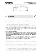
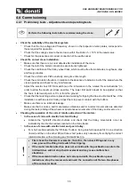
2) Sling the thrust bearing and place it on the upper plate of the column matching up the holes (fig. 34).
3) Insert the supplied bolts from the top and tighten them with the correct torque (see table).
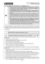
4) Place the supplied spacer flange above the thrust bearing coupling the hole (fig. 35).
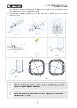
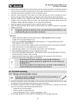
5) Sling the arm in the points as indicated in (fig. 36) and lift it with means suitable for the purpose, i.e.
bridge crane or mobile crane and relative slings with adequate capacity and specifications in relation
to the weight to move, being careful to maintain the beam horizontal to the ground.
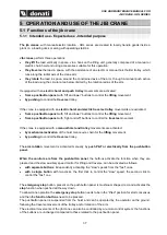
6) Avoid swinging and tilting and, if necessary, to maintain equilibrium use a rope or cord tied to the end
of the arm (fig. 37).
7) Place the arm with perforated plate on the thrust bearing matching up the holes (fig. 38).
8) Insert the longest screws with connected flat washer from the top in the side drilled holes (not threaded)
and tighten with nut and PAL nut.
9) Insert the shortest screws with connected elastic/Groover (penso che questo dovrebbe essere Grower
oppure split washer, grower type) washer from the bottom of the threaded holes (present under the
beam).
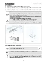
10) Tighten all bolted joints with a dynamometric spanner following the couples shown in the figure on the
next page.
Manual rotation model
11) Cover the gear motor housing hole with the relative cover (supplied) and tighten it with the supplied
screws.
Electric rotation model
11) Mount the gear motor (make sure that the pinion teeth have been greased) inserting it in its seat and
checking that it is perfectly settled (fig. 39). If this operation becomes difficult, due to imperfect alignment
of the pinion teeth and thrust bearing, slightly turn the arm until the point where there is correct coupling
of the teeth.
12) Insert the 4 TCEI M10 screws in the flange holes and tighten with a torque equal to 32 Nm.
fig. 34
TORQUE FOR THRUST BEARING
BOLTS
M14 class 8.8: 135 Nm
M16 class 10.9: 288 Nm
fig. 35
Содержание GRL Series
Страница 2: ......
Страница 14: ...USE AND MAINTENANCE MANUAL FOR JIB CRANE GRL SERIES 10 Fixing systems for jib cranes ...
Страница 64: ......

