Installation, Operation and Maintenance manual
16
DFPRE 6L Dust Collectors
OPERATION
On installations where the inlet duct is relatively short, this procedure may
result in a dust emission occurring at the inlet and therefore may not be an
appropriate procedure if the dust being handled is dangerous. Therefore a Risk
Assessment must be carried out to ensure the final procedure is safe.
Principle of operation
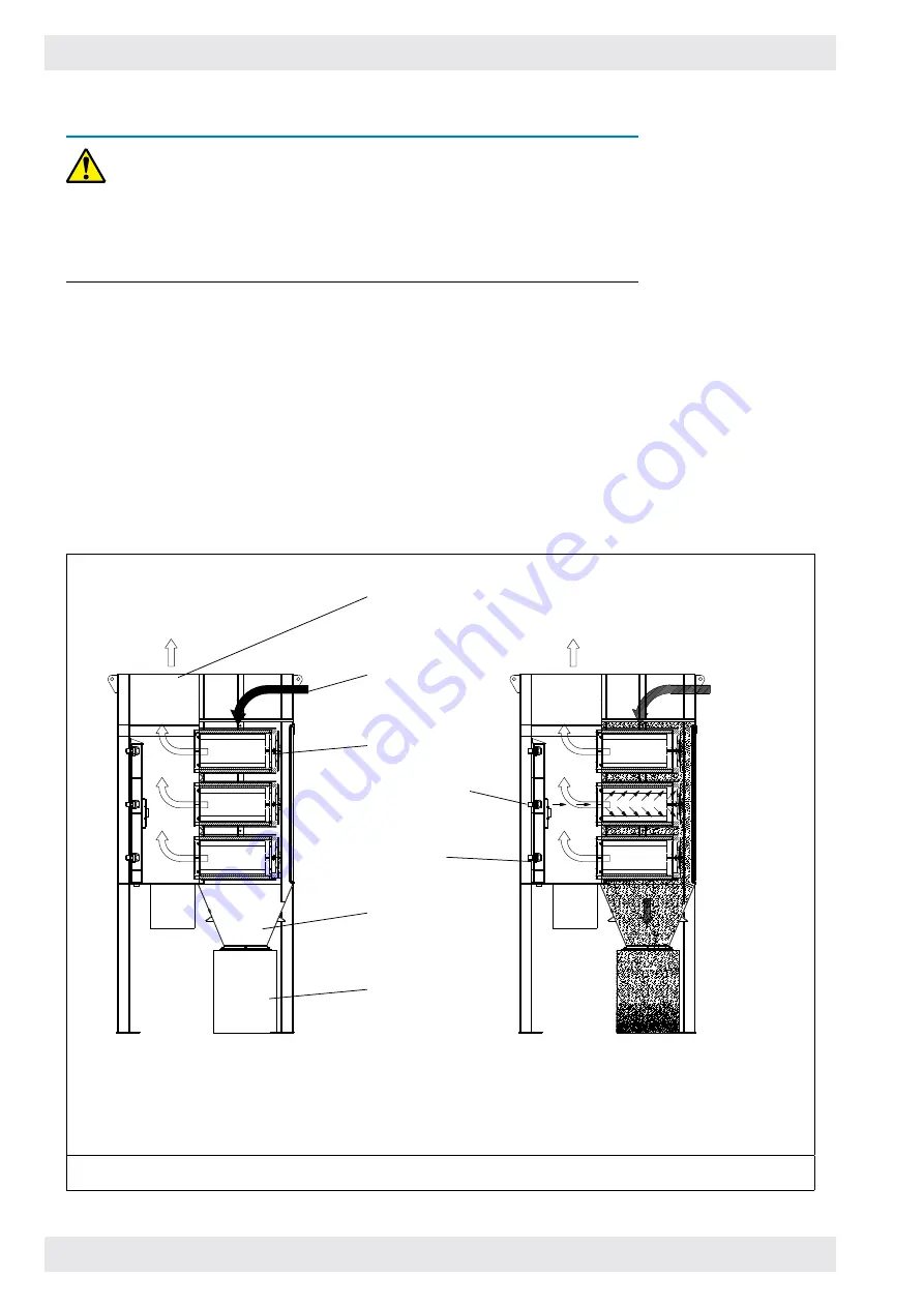
(Refer also to figure 4).
Contaminated air from the dust generation source is drawn through the inlet to the
collector by the fan. Airflow is directed through the collector and heavier particulate
falls directly into the hopper. The cartridges remove the fine particulate and clean,
filtered air passes through the cartridge to the clean air chamber and discharges
through the clean air outlet.
At regular intervals, governed by the controller, each cartridge in turn receives a short
burst of compressed air from an adjacent air diaphragm valve. These valves are at an
optimum distance from the cartridge, ensuring that a large volume of air is induced
by each injection of compressed air, causing a brief, powerful reversal of airflow
through the cartridge, effectively dislodging the dust layer which then falls into the
discharge hopper.
b Cleaning operation (intermittent)
(Each cartridge is cleaned separately, in turn)
a Filtering operation (continuous)
Hopper
Dust container
Cleaned air
outlet
Contaminated
air inlet
Cartridge
Compressed
air manifold
Diaphragm valve
Figure 8: Principle of operation


