background image

REFERENCE

5--34

27080 Issue 1 August 98

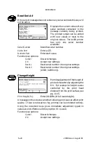
%A

Date (01 to 31).

%B

Julian date (001 to 366).

%C

Julian year (0 to 9).

%D

Year (00 to 99).

%E

Year (1970 to 2038).

%F

Month (01 to 12).

%G

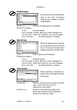
Month name (see pg. 5--33).

%H

Hours (00 to 23).

%I

Quarter hours (01 to 96).

%J

Day name (see pg. 5--32).

%K

Week number (01 to 53).

%L

Day number (1 to 7).

%M

Minutes (00 to 59).

%N

Seconds (00 to 59).

%O

Alpha hours (see pg. 5--33).

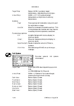
Function key options:

Cancel

Discard changes.

Add/Replace

Accept new settings.

Delete

Delete format.

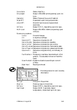
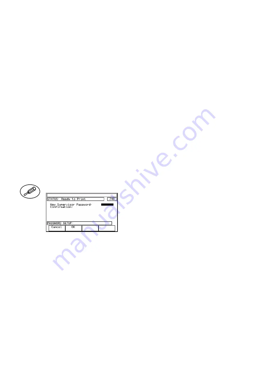
Password Setup

Permits the Supervisor password
to be changed and password
protection to be enabled or
disabled.

When the screen is opened the

New Supervisor Password

is empty.

Entering a password enables the password protection of all Supervisor
controlled areas (see pg. 2--13). Using key option

OK

immediately

without any entry disables the password protection.

New Supervisor Password:

Enter alphanumeric

characters.

Use the cursor keys to move the highlight bar down.

Confirmation:

Enter exact repeat of new password and
press

OK

.

The new and confirmed passwords must be identical to be accepted.
Function key options:

Cancel

Discard changes.

OK

Accept new settings.

Содержание A-SERIES

Страница 1: ...DOMINO A SERIES INK JET PRINTER OPERATION AND MAINTENANCE MANUAL ...

Страница 2: ... 2 1992 Class B Electromagnetic Compatibility Conducted EN50082 2 1992 Electromagnetic Compatibility General Immunity Standard EN55022 1 1987 Class A Electromagnetic Compatibility Radiated EN60204 Part 1 Safety of Machinery Electrical Equipment of Industrial Machines EN60950 Safety of Information Technology Equipment including Electrical Business Machines following the provisions of 73 23 EEC Low ...

Страница 3: ...cial warnings or requirements It is therefore essential that users are also familiar with these symbols and act accordingly All rights reserved No part of this publication may be reproduced stored on a retrieval system or transmitted in any form or by any means electronic mechanical photocopying recording or otherwise without the prior permission of Domino UK Ltd Domino UK Ltd has a policy of cont...

Страница 4: ...y to cause harmful interference in which case the user will be required to correct the interference at his own expense If this equipment does cause harmful interference to radio or television reception which can be determined by turning the equipment off and on the user is encouraged to try to correct the interference by one or more of the following measures D Re orientate or relocate the receivin...

Страница 5: ...ng Part 5 Reference Glossary of terms and screen descriptions with details of the options CHAPTER 3 Part 6 Printer Description Print head cabinet electronics and ink systems Part 7 Maintenance General and periodic maintenance jet alignment and ink changes Part 8 Repair Print head electronics system and ink system Part 9 Spares and Accessories Accessories consumables tools and spares Part 10 Option...

Страница 6: ... 6 27080 Issue 1 Sept 98 ...

Страница 7: ...8 7 DOMINO A SERIES INK JET PRINTER OPERATION AND MAINTENANCE MANUAL AMENDMENT RECORD Amendment Date All Parts at Issue 1 September 98 Appendix B Compressor Driven Airdryer April 98 Appendix B Air Driven Airdryer April 98 ...

Страница 8: ... 8 27080 Issue 1 Sept 98 ...

Страница 9: ...NENT DOMINO PART NO MANUFACTURER MANUFACTURER PART NO HV PSU 12170 Advance HI Volt GM7 19 PSU Assy 37758 Bulgin Power Source SAX110 34 Filter Mains Power 13492 Shaffner Bulgin FN332 3 05 PS02 A0320 63 Switch Mains Power 37744 EAO 61 8420 12 Plug 3 Way Mains Power 13496 Bulgin PX0730 P Socket 7 Way Mains Power 13498 Bulgin PX0744 S PCB Assy External Interface 25109 Domino 25109 Fuse 20x5 T 1A 01210...

Страница 10: ... 10 27080 Issue 1 Sept 98 ...

Страница 11: ...27080 Issue 1 August 98 1 1 PART 1 HEALTH AND SAFETY CONTENTS INTRODUCTION Page 1 3 Basic Requirements 1 3 Storage 1 4 Fire Risk 1 4 Spillages and Disposal 1 6 SYMBOLS 1 7 ...

Страница 12: ...HEALTH AND SAFETY 1 2 27080 Issue 1 August 98 ...

Страница 13: ...ontact with inks must be properly instructed in their use Directions for safe working practices vary according to the environment The following are broad principles so that necessary precautions may be taken D Contact with the mouth must be avoided Therefore eating drinking or smoking or any personal habits or actions which may transfer ink to the mouth must be avoided D Contact with the eyes must...

Страница 14: ... which have previously been used at any time for any other purpose In other words a printer using food grade ink can be converted for use with other inks but a printer which has used other inks must not be converted for use with food grade ink Storage Printing inks must be stored in well ventilated buildings or in areas set aside for the purpose chosen for safety in case of fire Materials based on...

Страница 15: ...lammable residue Solvent based inks offer a greater degree of hazard depending on the particular solvent or solvent combination When there is a particular hazard the appropriate information is given on the SDS Ink jet printers place small electrostatic charges on the ink drops used for printing In most circumstances such as when they arrive at the print surface these electrostatic charges are eith...

Страница 16: ...lvent materials and with regard to the safety of personnel Care must be taken to prevent spillages or residue from cleaning up entering drains or sewage systems Inks and associated fluids are materials which conduct electricity Therefore power to the printer must be switched off while spillages inside the printer cabinet are being cleaned up Printing inks and associated fluids must not be treated ...

Страница 17: ...n The equipment must be switched off and power removed Only trained personnel should carry out this procedure Beware of Electrostatic Discharge ESD Electrostatic precautions must be used D Switch off machine first D Wear a wristband connected to ground D Avoid wearing clothing which can build up electrostatic voltages D Use ESD protective bags to transport PCBs D Only place PCBs on a mat made from...

Страница 18: ...HEALTH AND SAFETY 1 8 27080 Issue 1 August 98 ...

Страница 19: ...nput 2 6 Ink System 2 7 Environment 2 7 General 2 7 PRINTER CONTROL 2 8 Front Control Panel 2 8 Display 2 8 On Off Switching 2 9 Topic Keys 2 11 General Purpose Keys 2 12 Help Key 2 13 Currency Key 2 13 Password System 2 13 Unicode Character Entry 2 14 Importing and Exporting Data 2 14 User Port 2 14 FRONT PANEL TOPIC KEY MENUS 2 15 ...

Страница 20: ......

Страница 21: ......

Страница 22: ......

Страница 23: ...e front panel D A full description of the ink and electronics systems D Maintenance and repair procedures The printer consists of a printhead connected to a stainless steel cabinet by way of a flexible conduit The cabinet contains an ink system and a controlling electronic system operated through a panel on the cabinet upper door The printers are shown on pages 2 2 2 3 and 2 4 with internal views ...

Страница 24: ...Pinpoint and A100 3m only Cabinet Standard Finish Brushed 316 stainless steel A300 Brushed 304 stainless steel A200 A100 IP Rating A300 is IP65 1977 A200 A100 are IP53 1977 Dimensions A300 A200 Width 475mm 18 7 not incl handles Depth 245mm 9 65 not incl front panel Height 715mm 28 15 not incl feet Weight A300 A200 incl fluids 36kg 79lbs Dimensions A100 Width 450mm 17 7 not incl handles Depth 245mm...

Страница 25: ...storage wet dependent upon fluids Humidity 10 90 RH non condensing Electrical Supply 90 132V 180 264V 50 60Hz single phase Auto ranging 200VA internal fuse rating 4A General Acoustic Noise Level Not more than 70 dBA Positive Air Pressure print head Internal or external supply Max external supply pressure to cabinet 1 bar A100 is internal only Product detector Shaft encoder connectors Bulgin Buccan...

Страница 26: ... keys D Function keys with functions which can change under software control The main areas of the front panel are identified in the diagram below Topic Keys Cursor Keys Increment Keys Jet On Off Key Data Entry Keys Function Keys Display Front Panel Keyboard Layout Character Set Keys A1006_1 Display The display presentation has the following basic structure Alert bar shows a message when a printer...

Страница 27: ...en there is morethanfour key options Scrolling resultsin thekey labelschanging with the functions of the keys also changing to correspond with the labelling Screen number provides a numerical identity for each screen Scroll arrow shows that the screen detail extends off the display The up and down cursor keys must be used to show the hidden detail Print symbol shows printing as each Print Go signa...

Страница 28: ...ber Alert Indicator shows the printer has a fault that requires attention The indicator flashes while the alert is unacknowledged and displays steadily when the alert is acknowledged It is extinguished when the fault is cleared Green Indicator flashes while the printer is starting up or shutting down and displays steadily when the printer is printing or ready to print It is extinguished by a fault...

Страница 29: ...ssage Store Provides access to the stored Messages Print Setup Provides access to the utilities controlling the message being printed e g message orientation Machine Setup Provides access to adjustments in setting up the printer Service Provides access to the printer for the Service engineer Memory Card Provides access to the PCMCIA utilities Message Monitor Shows the message currently being print...

Страница 30: ...unctions identified by the names in the keybar immediately above Delete Key Deletes entries marked by the highlight bar Alternative Character Set Left Blue Press this key to select the top left blue character on each character key Also used with the and keys controls screen contrast Alternative Character Set Right Green Press this key to select the top right green character on each character key S...

Страница 31: ...printed by pressing the Label Monitor key Access to all other functions requires the use of the appropriate password provided this has been set The Lockout screen also shows the internal clock which is replaced in all other cases by a screen number Password System Entry to the Lockout and Message Monitor areas of printer control is unrestricted but all other areas can if required be protected by p...

Страница 32: ...tted PCMCIA card which can be used to copy and back up messages and logos This can then be used as a back up for the messages and logos or used to copy messages and logos to another printer It is possible to copy the entire message see pg 5 30 or logo store or individual messages or logos see pg 5 23 and 5 25 Back up Restore Card The Back up Restore card is a dedicated PCMCIA card used to back up ...

Страница 33: ... Select Raster Select Message Print Message Stop Msg Printing Save Message Delete Message Storage Stats Export Message Import p Import r Logo Store Stop All Printing MESSAGE STORE pg 5 16 pg 5 17 pg 5 18 pg 5 19 pg 5 19 pg 5 20 pg 5 20 pg 5 21 pg 5 21 pg 5 21 pg 5 22 pg 5 22 pg 5 23 pg 5 23 pg 5 23 pg 5 24 pg 5 24 pg 5 25 LOGO STORE Cancel OK Delete Logo Storage Stats Export Logo Import p Import r...

Страница 34: ... I F Cancel OK Product Sequence Start Product End Product Print Once Exit Start Sequence Start Cont Stop PRODUCT SEQUENCE SIMULATION Pg 5 30 pg 5 30 pg 5 30 pg 5 30 pg 5 31 pg 5 31 pg 5 32 pg 5 32 pg 5 32 pg 5 33 pg 5 33 pg 5 33 pg 5 34 pg 5 35 pg 5 35 Pg 5 44 pg 5 37 pg 5 38 pg 5 39 pg 5 41 pg 5 42 pg 5 43 pg 5 43 pg 5 44 pg 5 44 Front Panel Topic Key Menus Message Bold Reverse Control Inverse Co...

Страница 35: ...E 3 7 Display Contrast 3 7 General Information 3 7 Creating the Message 3 8 To Print the Message 3 8 To Save the Message 3 8 To Delete the Message from Store 3 8 To Select an Existing Message 3 9 To Enter a Clock Entry 3 9 To Enter a Serial Number 3 11 To Enter a Shift Code 3 12 To Enter a Text Field 3 12 To Create a Machine Readable Code 3 13 Repl Resv Repl Cart Create Msg ...

Страница 36: ...OPERATION 3 2 27080 Issue 1 August 98 ...

Страница 37: ...ched on Press the Jet On Off key for 2 3 seconds or until an audible beep is heard if activated see pg 5 35 Turning on the jet is an automatic procedure taking about 70 seconds D Status bar shows the message Sequencing On D Green indicator on the Jet On Off key begins to flash D Status bar message changes to Ready to Print green indicator shows steadily The printer is now ready to print messages S...

Страница 38: ...quality code 5 Press the function key marked OK If the correct code is typed in the reservoir run time will be reset and the alarms cancelled Proceed to step 6 If the number is typed inaccurately it can be corrected by typing in again If an invalid code number is typed the number will not be accepted and messages in the information bar will indicate the problem e g Incorrect ink type Ink out of da...

Страница 39: ...OPERATION 27080 Issue 1 August 98 3 5 Manifold Retainer Reservoir Retaining Bar Reservoir Retaining Bar Refitting the Ink Reservoir Removing the Ink Reservoir MG187 1 MG188 1 MG189 1 ...

Страница 40: ...ted anti clockwise and the make up is rotated clockwise to free them before being lifted away This mechanism ensures that the cartridges cannot be fitted onto the wrong manifold To fit a cartridge cut off the sealing tab and push on to the correct manifold Cartridge Replacement Rotate and lift cartridges to remove Press cartridge down firmly to fit MG186 2 MG184 1 MG183 1 If the make up cartridge ...

Страница 41: ...cter type in the new character without moving the highlight Font character size bold characters and double spacing can be selected as function key options Pressing the key activates the option and all subsequent entries will be size bold spaced accordingly until the key is pressed again Values can be typed in or changed by using the incrementkeys see pg 2 12 Values changed with the increment keys ...

Страница 42: ...he message will now be printed at each Print Go signal if the printer is in the Ready to Print state Note If an on line message is changed in any way it is necessary to press Print Message again to implement the changes To Save the Message 1 Press the Message Store key The screen will change and may show the name of a previous message ignore this 2 Select Save Message from the key options along th...

Страница 43: ... of the required message 3 Select OK from the key options The display will change to show the name of the chosen message only Note To print this message select Print Message from the key options 4 Press Message Editor and the display will show the full message To Enter a Clock Entry 1 With Message Editor selected select Insert Clock from the key options The display will change to show the Insert C...

Страница 44: ...the key options The display will change to show the message with the clock detail inserted at the cursor position Clock entries on the display will not be updated However the printed messages will have clock entries updated from the master clock and Message Monitor will also display the correct clock information after each received print go OK ...

Страница 45: ...king on A300 A200 only In the case of alphanumeric serial numbers the order precedence in which the alpha and numeric parts are updated can be selected In the following steps the example entries will create a serial number AA0000 AA0001 through AX0000 up to KK1000 increasing at each step by 1 2 Use down and up cursor keys to move the highlight bar and select the details of the serial number and ty...

Страница 46: ...he key options The display will change to show the message and provided the current real time falls within the specified shift code start and stop times the shift code name e g Red will be inserted at the cursor position If the shift code time is outside the time limits the shiftcode position in the message will show as a blank space To Enter a Text Field A text field is a blank area which can be ...

Страница 47: ...datesto theMRCwill then beautomatically applied to the human readable text During the procedures key labels along the bottom of the screen may not show the required options It will be necessary to be familiar with using the scroll keys see pg 2 12 to move the key options across the screen and selecting an option by pressing the key below the label on the screen It will also be necessary to be fami...

Страница 48: ...to step 4 allowing the barcode details to be changed Alternatively toggling to the barcode and selecting Edit also returns the screen in step 4 7 The barcode data can be printed in human readable form either before or after the barcode or it can be indented into the barcode as shown in the diagram Some barcodes such as EAN 13 use a double indentation Select Advanced 8 With Advanced selected set th...

Страница 49: ...adable characters would be placed in the two positions Select MRC Text 19 Select Number of Characters and enter the number of characters to be put into the first indent this is usually half of the total number Leave the Offset value at zero 123456789123 First indent characters Second indent characters Offset 123456 789123 20 Select OK and check that the required characters appear in the first inde...

Страница 50: ...c only 0 9 2 Upper case only A Z 2 Alpha only A Z 3 Lower case only a z 3 Printable ASCII 4 Punctuation 5 Alphanumeric A Z a z 0 9 Error Correction Code ECC applied to dotcode Use the help to enter the required ECC for Snowflake values of none and checksum are not permitted and will be changed to the minimum supported value of 10 For Data Matrix ECC values of 000 010 and 040 are not supported and ...

Страница 51: ...4 6 4 11 x 24 23 19 19 23 15 12 x 12 8 7 7 8 5 12 x 24 26 21 21 26 17 13 x 13 12 9 9 12 8 14 x 14 15 12 12 15 10 15 x 15 17 13 13 17 11 16 x 16 21 17 17 21 14 16 x 24 39 31 31 39 26 20 Error Code Correction DENSITY MAXIMUM CHARACTER ENCRYPTION CAPACITY DENSITY Numeric Format 1 Upper Case Format 2 Lower Case Format 3 Punctuation Format 4 Alphanumeric Format 5 7 x 16 2 2 2 2 1 7 x 24 6 5 5 6 4 8 x 8...

Страница 52: ...SITY Numeric Format 1 Upper Case Format 2 Lower Case Format 3 Punctuation Format 4 Alphanumeric Format 5 7 x 16 n a n a n a n a n a 7 x 24 2 2 2 2 1 8 x 8 n a n a n a n a n a 9 x 9 n a n a n a n a n a 10 x 10 n a n a n a n a n a 11 x 11 1 n a n a 1 n a 11 x 24 6 5 5 6 4 12 x 12 1 1 1 1 1 12 x 24 7 5 5 7 4 13 x 13 2 1 1 2 1 14 x 14 2 2 2 2 1 15 x 15 4 3 3 4 2 16 x 16 5 4 4 5 3 16 x 24 11 9 9 11 7 ...

Страница 53: ... Format 1 Alphanumeric Format 2 ASCII Format 3 13 x 13 4 3 2 15 x 15 13 9 6 16 x 16 13 9 6 Error Code Correction 100 DENSITY MAXIMUM CHARACTER ENCRYPTION CAPACITY DENSITY Numeric Format 1 Alphanumeric Format 2 ASCII Format 3 13 x 13 1 1 n a 15 x 15 8 5 3 16 x 16 8 5 3 Error Code Correction 200 DENSITY MAXIMUM CHARACTER ENCRYPTION CAPACITY DENSITY Numeric Format 1 Alphanumeric Format 2 ASCII Format...

Страница 54: ...s 4 3 Amber alerts 4 3 Fault Acknowledgement 4 4 ALERT BAR MESSAGES 4 4 STATUS BAR MESSAGES 4 14 INFORMATION BAR MESSAGES 4 16 PRINTER FAULTS 4 17 No Indicators Showing 4 17 Machine Does Not Print 4 17 Print Position Incorrect 4 17 Print Size Too Small 4 18 Gutter Over flowing Ink 4 18 PRINT QUALITY FAULTS 4 19 ...

Страница 55: ...DISPLAY MESSAGES AND FAULT FINDING 4 2 27080 Issue 1 August 98 ...

Страница 56: ...will show continuously If the fault condition has cleared when acknowledged the red LED will extinguish and the message will be removed Recoverable The green LED on the jet on off switch will flash as the printer attempts to recover The jet remains switched on If recovery is successful the green LED will remain on and the red LED will flash until acknowledged When acknowledged the red LED will ext...

Страница 57: ...always at a higher priority than any acknowledged alert All reports are recorded in the error log together with times of acknowledgement and repair ALERT BAR MESSAGES Alert Bar The following warning and alert messages may be displayed Abandoned message product ended End of product detected before end of message Check sensor position message length Abnormal ink pressure Ink pressure is outside limi...

Страница 58: ...oir Blank message detected no drops Attempting to print a blank message Edit message or reassign a message containing information Cabinet overheated Cabinet temperature is too high Ensure printer is operating within specified temperature environment Check air filter If fault persists call Domino Service Cabinet temperature sensor input error Failure at input to sensor If fault persists call Domino...

Страница 59: ...r Send new message EEPROM write failed The EEPROM a hardware device used by the printer to store the ink life data has failed If fault persists call Domino Service Excess pump overspeed Ink pressure is being maintained but pump speed is excessive Check ink system for leaks or worn pump Excess pump underspeed Ink pressure is being maintained but pump speed is too low Check ink system for blockages ...

Страница 60: ...omino Service Fault PEB restarted Internal error If fault persists call Domino Service Fault PSB restarted Internal error If fault persists call Domino Service Fault SGB restarted Internal error If fault persists call Domino Service Gunbody temperature high Gunbody temperature is higher than set value If fault persists call Domino Service Gunbody temperature low Gunbody temperature is lower than s...

Страница 61: ...sue 1 August 98 Ink temperature sensor input error Failure at input to sensor Check sensor connections If fault persists call Domino Service Ink change due replace ink reservoir Ink life has expired Fit new reservoir before printing can be restarted ...

Страница 62: ...gs Ink detected on charge electrode Ink on charge electrode Clean charge electrode see pg 7 17 restart printer Ink hours to go data altered Ink life setting has been altered due to either ink being changed or ink life setting value adjustment Check authorisation for change Ink heating failed Ink heating system has failed Check heater connections and check thermistor Ink level sensor input error Fa...

Страница 63: ...This message is displayed for information only It indicates that a new file store for the display of messages logos etc has been created This may happen if the printer has been reconfigured to use a different ink type nozzle size or print format No ink Ink level is below minimum Fit a new ink cartridge No make up Make up level is below minimum Fit a new make up cartridge PEC config item defaulted ...

Страница 64: ...Check sensor connections If fault persists call Domino Service Print data generated too late Print rate too fast Adjust print delay Print failed print delay too short Message data was not received before the next product was detected Increase print delay until an acceptable value can be entered If necessary adjust position of product sensor or print head If fault persists call Domino Service Print...

Страница 65: ... for excess or loss of pressure Check for blockages or leaks in ink circuit Pump pressure could be set too high Check and adjust if necessary Quality code OK fit reservoir Quality code indicates a reservoir of the correct type Fit reservoir RAM disk has been reformatted File store has been re initialised with loss of any changes to configuration parameters and edited messages Possible battery back...

Страница 66: ...e switch has failed or if fitted the air supply from the air dryer has stopped Check fan and connections Viscometer fault Viscometer or valve has failed Check connections replace viscometer or valve Viscosity out of range Make up cartridge empty or make up add solenoid failed Printing is still possible but print quality may deteriorate Replace make up cartridge or solenoid Ensure printer operating...

Страница 67: ...ver from and it is attempting to do so Please wait until the printer reports Ready to Print indicating that recovery was successful or the printer aborts the recovery attempt and sequences off Head bleed in progress The printer is performing a print head bleed operation This is a service level operation Heating please wait During sequencing on the printer has determined that the gunbody in the pri...

Страница 68: ...is is one of the possible states that printer can enter when first turned on the other is Printer Standby Printer Initialising The printer is initialising This may take several minutes if the printer has been reconfiguredto operateusing differentoperating parameters e g the ink type nozzle size or print format has changed Printer Standby The printer s ink delivery system is sequenced off but the i...

Страница 69: ... normal operation this state is reported when the operator has requested sequence on to get Ready to Print INFORMATION BAR MESSAGES Information Bar This bar normally shows the current menu name but is also used to provide general messages such as the following Such messages are normally self explanatory Access Denied Action Not Allowed Discard Changes Leave Dialog First File Already Exists Overwri...

Страница 70: ...Check data entry Product detector disconnected or faulty Check detector Width control set too low Reset width control Faulty Shaft Encoder Check shaft encoder and connector External stroke source selected where no encoder is fitted Change to internal stroke source see pg 5 42 Print Position Incorrect Print delay incorrect Re enter Print delay data Product detector misaligned Re align detector Spac...

Страница 71: ...quired Solvent on deflector plates after cleaning Dry deflector plates Print head too close to product Check position of print head Incorrect size nozzle fitted Check and replace if necessary Gutter Over flowing Ink Gutter filter blocked Replace gutter filter Gutter tube blocked Wash down and clear gutter Air leak preventing vacuum at gutter Check gutter circuit for leaks Vacuum pump head faulty C...

Страница 72: ...operly aligned Head not mounted at 90 degrees to direction of product movement Head too far from print surface Pressure too low note missing drops from some characters Pressure too high note drops coalescing on some characters Incorrect break up satellites can be seen in the viewer and break up is not in correct position relative to charge electrode Printed drops clipping edge of gutter jet incorr...

Страница 73: ... Number 5 9 Advanced Serial Number 5 10 Edit 5 11 New Message 5 11 Bold On Off 5 11 DblSpace On Off 5 12 Shift Code 5 12 Insert Logo 5 12 Text Field 5 13 Clock Offsets 5 13 Start MRC 5 14 End MRC 5 14 MRC Text 5 15 Toggle MRCs 5 16 Special Setup 5 16 SPECIAL SETUP 5 16 Message Bold 5 16 Reverse Control 5 17 Dynamic Control 5 17 Counted Repeats 5 17 Counted Products 5 18 Inverse Control 5 18 Repeat...

Страница 74: ...go Store 5 24 Delete Logo 5 24 Storage Stats 5 25 Export Logo 5 25 Import p 5 25 Import r 5 25 Stop All Printing 5 25 PRINT SETUP 5 26 Message Bold 5 26 Reverse Control 5 26 Inverse Control 5 26 Repeat Printing 5 26 Enable Printing 5 27 Print Delay 5 27 Reset Serial Number 5 28 Change Height 5 28 Change Width 5 29 MEMORY CARD 5 30 Export Messages 5 30 Import Messages 5 30 Export Logos 5 30 Import ...

Страница 75: ...s 5 32 Month Names 5 33 Alpha Hours 5 33 Time Format 5 33 Password Setup 5 34 Set Currency 5 35 Beeper 5 35 SERVICE 5 36 Print Head 5 37 Ink System 5 38 Viscosity 5 39 External I F 5 41 Config 5 42 Event Log 5 43 Change Resvr 5 43 Backup Printer 5 44 Product Sequence Simulation 5 44 ...

Страница 76: ...REFERENCE 5 4 27080 Issue 1 August 98 ...

Страница 77: ...ocedure MRC Machine Readable Code such as barcode or Dot Code PCMCIA Personal Computer Memory Card International Association the software interface and hardware specification for the memory and input output cards used by the printer Range Information presented by the printer the range within which the value should appear Raster The set of charge voltages that create a print stroke Rasters are spec...

Страница 78: ...trokes is sometimes used as a unit of measurement in spacings or delays Unicode An international coding scheme for written characters and text each of which is identified by a 16 bit code between 0000 and FFFF The code conforms to a Standard maintained by the Unicode Consortium and ISO organisation Print Definitions Print Go Print Delay Normal Print Print Delay Inverse Print Bold Double Stroke Pri...

Страница 79: ... complete numbers or replaced by values typed in using the keys However when values are being entered the highlight bar is confined to single characters and has to be moved using the left and right cursor keys accordingly Highlighted characters can be removed with the delete key and typed characters will be inserted to replace them Repeated use of the delete key will deleted the highlighted charac...

Страница 80: ...te and modify messages Existing entries are marked with a highlight bar and the highlight bar is moved around the message using the cursor keys A cursor of the selected character size appears at the end of line position Entries can be made into the message as shown below For very accurate print positioning a thin space can be inserted using Shift and Space keys Print Message Permits the message be...

Страница 81: ...us menu without entering clock OK Enter clock information into message Serial Number Permits creation of a serial numbering system and inserts it into the message at the cursor position Numbers can be numeric or alphanumeric using Advanced Numbers with a first limit higher than the second limit will decrement Two serial numbers are available on the A300 A200 printers and one on the A100 printer Fi...

Страница 82: ... to be carried across into a second serial number A300 A200 only Precedence Select Numeric Alpha to select which part of the number will be the least significant part i e successively updated with the step size First Limit Enter alpha characters in range a ZZ as starting value of sequence Second Limit Enter alpha characters in range a ZZ as finishing value of sequence Lower Character Enter alpha c...

Страница 83: ...cel Discard changes OK Accept new settings New Message Clears the screen to start a new message If the current message has been edited but not saved a warning is given so that if required the current message can be named and saved before being discarded Current Message Shows name of current message Discard Changes If selected with the highlight bar the changes to the message can be discarded Optio...

Страница 84: ...g time in 24hr clock system String Enter shift code name identification code etc Function key options Cancel Return to previous menu without entering a shift code OK Enter shift code into message Insert Logo Permits the selection of a logo from the logo store and inserts it at the cursor position The logo name is shown on the display If heightand width values are set the logo is centred within the...

Страница 85: ...d settings Clock Offsets Permits setting offsets into each of four clocks A300 A200 two clocks A100 derived from the master clock These clocks numbered 1 to 4 1 to 2 can then be used by date time fields see pg 5 9 If real master clock time is required for entry into messages one of the four two clocks must be left without offsets Offset Number Enter 1 4 1 2 Year Offset Enter 0 99 Day Offset Enter ...

Страница 86: ...o permits selection of the type of MRC and identifies the MRC as first second etc in the message Further MRC parameters can be set in Advanced see below Machine Readable Code Identifier Shows MRC identification number Code Type Select 2 5 5 BARCODE INTERLEAVED 2 5 BARCODE CODE 39 BARCODE EAN 13 BARCODE EAN 8 BARCODE UPC A BARCODE UPC E BARCODE CODE 128 BARCODE 2 5 INDUSTRIAL BARCODE Function key o...

Страница 87: ...ck digit Type depends upon type of barcode selected Function key options Cancel Return to previous screen without accepting changes OK Accept new settings MRC Text A300 A200 only Permits the characters represented by the MRC to be printed in human readable form The number of characters can be selected and the characters identified by specifying an offset of non printed characters see diagram pg 3 ...

Страница 88: ...l settings put in through Print Setup see 5 26 SPECIAL SETUP Provides access to the options permitting special settings for use with the message currently being edited see above Function key options Exit Return to the topic screen Others as below Message Bold Permits setting the message to be printed in boldand or withdouble spacing Alternatively the global bold setting selected through Print Setu...

Страница 89: ...ly applied and suspended to groups of messages The size of the groups is specified as message repeats or counts of products Reverse Orientation Select On Off Function key options OK Accept special settings Cancel Discard new settings Counted Repeats Open Counted Repeats screen Counted Products Open Counted Products screen External Port Provides access to external control settings Counted Repeats P...

Страница 90: ...hich reverse printing will be alternately applied and suspended Initial Orientation Select On Off for initial reverse printing Count Enter number of products Function key options Cancel Discard new settings and return to Special Setup screen OK Accept special settings Static Control Abandon dynamic control and return to Dynamic Control screen Counted Repeats Opens Counted Repeats screen see previo...

Страница 91: ...mbers for each repeat Select Yes No Use Product End Select Yes No Options Use Global Use the settings in Print Setup Counted Use Repeat Count value Continuous Repeat continuously Function key options Cancel Discard changes OK Accept new settings Message Offset Permits entry of an offset between the normal start of print position and the required print position This delay is added to the Print Dela...

Страница 92: ... allocation of a number to identify the message This allows a range of messages to be available for printing according to selection by number through the User Port Product Select Number Enter 0 255 Function key options Cancel Discard change OK Accept new setting Raster Shows the raster identification Special Setup Special Setup ...

Страница 93: ...wn the list by one screen use the shift key together with the up and down cursor keys To move to the start or finish of the list use the blue character set key together with the up and down cursor keys Function key options Cancel Return to previous menu OK Load selected message Print Message Permits the message currently selected to print on receipt of the next product detect signal Serial numbers...

Страница 94: ...d name Delete Message Permits deletion of any message from the message store except a message currently being printed marked If the message currently being printed is to be deleted printing must be stopped in Message Editor Function key options Cancel Return to previous menu without deleting message Delete Message Delete highlighted message Screen will change to request confirmation that selected ...

Страница 95: ...unction key options Cancel Return to previous menu Export Message Screen changes to show only the selected message Provides confirmation of selected message and permits entry of a filename for the file to be exported Path identity for the RAM disk is r Path identity for PCMCIA card is p Function key options Exit Return to previous menu without exporting file OK Export file and return to previous m...

Страница 96: ...of the store from which logos can be selected for insertion into messages Control of the logo store is similar to control of the messages in Message Store Logos are inserted into the message using Insert Logo see pg 5 12 Use the cursor keys to move the highlight bar to cover the logo Function key options Cancel Return to the topic screen OK Select logo and return to previous menu Others as below D...

Страница 97: ...for PCMCIA card is p Import p Permits import of a logo from the PCMCIA card into the logo store Import r Similar to Import p Permits import of a logo from the RAM disk into the printer for direct use in printing Stop All Printing Marks all messages as being not available for printing To mark individual messages as not being available for printing use Stop Message Printing see pg 5 21 Logo Store Lo...

Страница 98: ...stroke in a message Select Off On Function key options Exit Accept screen settings Reverse Control This function is similar to that in Special Setup see pg 5 16 Inverse Control This function is similar to that in Special Setup see pg 5 18 Repeat Printing Allows selection of continuous printing or a chosen number of repeated prints Repeated prints follow the print initiated by product detection and...

Страница 99: ...mits printing to be enabled under control of the product detector input Printing Select Enabled Disabled Function key options Exit Accept new settings Print Delay Permits entry of the delay in strokes between the print go input and the first stroke of the printed message Each print format has a minimum delay and the printer must not be set to values below this minimum see pg A 10 Print delay strok...

Страница 100: ...es OK Accept new settings Reset 1 Reset serial number 1 to original settings Reset 2 Reset serial number 2 to original settings A300 A200 only Change Height Permits adjustment of the height of printed characters by adjusting the HV Full scale print height is also controlled by the print head distance from the print surface see pg A 15 Print Height Enter 28 100 of full scale height A message on the...

Страница 101: ... but is adjusted by shaft encoder selection and the external stroke divider ratio see pg 5 41 Narrow Wide Width Limit Limits dictated by the print format Current Width Value Enter value between width limits Increase the value to reduce the width Using the increment keys gives immediate adjustment typed in values are not effective until key option OK is used Function key options Cancel Discard chan...

Страница 102: ...ard Any existing set of messages on the PCMCIA card will be overwritten Import Messages Permits import of a complete set of messages from the PCMCIA card If any message appears to already exist in the printer store the screen shows a prompt requesting confirmation that the imported message can overwrite the old message Function key options Cancel Return to previous screen without action Skip Do no...

Страница 103: ...ed Year Enter 1970 2038 Month Enter 1 12 Day Enter 1 31 Hour Enter 0 23 Minutes Enter 0 59 Seconds Enter 0 59 Function key options Cancel Discard changes OK Accept new settings Serial Port Permits the printer s serial port to be set up Baud Rate Select 1200 2400 4800 9600 19200 38400 Data bits Select 7 8 Stop Bits Select 1 2 Parity Select None Odd Even Normal settings are baud rate 38400 data bits...

Страница 104: ...ages The numbers are updated as products are detected and this will result in the numbers on the screen changing Products Detected Printed Up to 999999999 Function key options Exit Return to previous screen Reset Count Sets both counts to zero Day Names Permits editing of the day names used in the clock information inserted into a message using the message editor Day 1 2 Enter up to 28 alphanumeri...

Страница 105: ...associated with each of the 24 hours These can be inserted into a message using the message editor Hour 0 1 Enter 1 alphanumeric character Function key options Cancel Discard changes Save to Message Use new settings in current message only Save as Default Retain new names for use in new messages Msg Use Default Use default names in message Time Format Permits addition amendment or deletion of time...

Страница 106: ...ssword Setup Permits the Supervisor password to be changed and password protection to be enabled or disabled When the screen is opened the New Supervisor Password is empty Entering a password enables the password protection of all Supervisor controlled areas see pg 2 13 Using key option OK immediately without any entry disables the password protection New Supervisor Password Enter alphanumeric cha...

Страница 107: ...he upper and lower case currency key entries Major currency notes key Enter up to three alphanumeric characters as major currency Minor currency coins key Enter up to three alphanumeric characters as minor currency Function key options Cancel Discard changes OK Accept new settings Beeper Allows the beeper to be enabled or disabled when the beeper is enabled it sounds every time a key is pressed Be...

Страница 108: ...the printer Ink Temperature Range 5 55 C depending upon ink type Target BFT Dependent upon ink type seconds Actual BFT Result of last viscosity measurement seconds Reservoir Life Normally 600 hours Reservoir Hours Range 0 600 hours remaining before reservoir life expiry Head Temp Range 26 50 C depending upon ink type Ink Pressure Range 2500 3250 mbar depending upon ink type Pinpoint Range 3700 450...

Страница 109: ...0 1850 x100mV depending upon ink Mode Select Fixed Auto Set fixed only on Pinpoint Mod n Adjust Select 100mV 1V 10V increment key value when setting the modulation set point Mod n Setpnt Enter 250 1850 x100mV depending upon ink type nozzle size etc Ink Press Range 2500 3250 mbar depending upon ink type Pinpoint Range 3700 4500mbar depending upon ink type Conduit Compensat n Status 1 8 setting for ...

Страница 110: ...ges and returns display to previous screen Cancel Discards changes and returns display to previous screen Reset Modulat n Resets modulation when AUTOset is selected Print Once Simulates single Print Go to print single message Ink System Provides general ink system information Target Press Enter 2500 3250 mbar depending upon ink type or 3700 4500mbar for Pinpoint Actual Press Within 50mbar of ink s...

Страница 111: ...ences ink system to standby Seq to Jet Run Sequences ink system to jet running Seq to Modulate Sequences ink system to modulating state Seq to Phase LokSequences ink system to phase locked state Sequence On Sequences ink system fully on to Ready to Print Fast Shutdown Emergency crash stop fast shutdown of ink system This shutdown does not flush the head Reset Modulat n Resets modulation according ...

Страница 112: ...ange lower limit on BFT seconds Make up Valve Status Open Closed Visc Valve Status Open Closed Peltier Mode Status Off On Auto Peltier State Status On Off Ink Level Status Empty Low OK High Make up Status Empty Low OK High Ink Press Range 2500 3250 mbar depending upon ink type Pump Speed Range 1700 2300 rpm depending upon ink type Function key options Exit Returns display to previous screen ...

Страница 113: ... External Internal will only be shown when Product Sequence Simulation see pg 5 44 is providing internal product detection Stroke Source Select Internal External external for shaft encoder Internal Stoke Rate Range 0 25600 Hz max limited by print width maximum value External Stroke Divider Ratio Enter 1 32 to divide down the external input stroke rate into reduced rate for printing Function key op...

Страница 114: ...e printer Print Format Print format used by the printer Ink System Ink type used in printer Sump Life Ink life in hrs Keyboard Keyboard used by the printer Language Language used by the printer Communications Protocol External communications protocol S W Part Software part number Revision Software revision number Function key options Exit Returns display to previous screen Keyboard Shows keyboard ...

Страница 115: ... hours mm Range 0 59 minutes x Event code a Event acknowledged r Event raised c Event cleared s Status changed Function key options Exit Returns display to previous screen Serial Download Downloads log onto PC through the serial port Change Resvr Permits entry of the reservoir quality code when a new reservoir is fitted Only the code for a new reservoir will be accepted Please enter quality code E...

Страница 116: ...creen will identify a function key with the label Restore and if selected two function keys will then be labled Yes and No allowing the reload to continue or be terminated Product Sequence Simulation Permits internal product detection by setting up a simulated product detect sequence This can can be limited to a specified number of products or if set to continuous allowed to run until stopped by t...

Страница 117: ...7080 Issue 1 September 98 6 1 PART 6 PRINTER DESCRIPTION CONTENTS PRINT HEAD Page 6 3 General Principles 6 3 Details 6 3 CABINET 6 5 ELECTRONICS SYSTEM 6 12 INK SYSTEM 6 16 General 6 16 Ink Circuit 6 16 ...

Страница 118: ...rator Head Valve Print Head General View MG055 2 Gutter Deflector Plates Charge Electrode Holster Securing Screw Magnifier Pinpoint print head Deflector Plates Charge Electrode Drop Generator Gutter TP1251_1 PRINTER DESCRIPTION 6 2 27080 Issue 1 September 98 ...

Страница 119: ...s adjusted to occur within the charge electrode where each ink drop is given an electrostatic charge by putting a voltage onto the charge electrode as the drop breaks off The size of the charge on the ink dropdependsuponthe voltageon thecharge electrode The ink drops then pass through the electrostatic field set up between between two high voltage deflector plates The direction of flight of each c...

Страница 120: ...s a bleed function which increases the ink flow through the drop generator and sweeps out any traces of air or solid material Jet break up The ink jet breaks up into separate drops within the charge electrode by careful control over the ink viscosity and the drive rod vibration The electronic system also maintains a close control over the timing of the charge voltages on the charge electrode relat...

Страница 121: ...is switched over from ink to make up The generator fills with make up and the jet becomes make up which cleans the nozzle and the gutter Any stray drops not collected in the gutter evaporate with very little residue At start up the make up in the gunbody is replaced with ink ready for the head solenoid to open Positive Air Supply Contaminants can be picked up by the ink drops in flight or be drawn...

Страница 122: ... in through the right side of the base and ducted up the right hand side wall through a filter into the upper electronics compartment Afan thenforces theair downthrough the lower ink compartment and out through the left side of the base A baffle plate on the underside of the cabinet prevents re circulation of the air A200 and A100 cabinets are cooled by air drawn in through louvres on the right si...

Страница 123: ...xternal Interface PCB LCD Assembly Front Panel PCB Fan Ink System Interface PCB Control PCB Assembly Power Supply HV Power Supply Mains Filter A300 A200 Cabinet General View 1 Viscometer Ink Management Block MG002 2 Air Filter Front Panel Cover not shown ...

Страница 124: ...8 A300 A200 Cabinet General View 2 Pump Air Filter Securing Latch Make up Cartridge Ink Reservoir Make up Reservoir Ink Cartridge Air Pump or Pressure Switch Options Peltier Condenser Assembly Optional on A200 Solenoid Valves MG003 2 Front Panel Cover ...

Страница 125: ... External Interface PCB LCD Assembly Front Panel PCB Fan Ink System Interface PCB Control PCB Assembly Power Supply HV Power Supply Mains Filter A100 Cabinet General View 1 Viscometer Ink Management Block A1001_1 Air Filter Front Panel Cover not shown ...

Страница 126: ...27080 Issue 1 September 98 A100 Cabinet General View 2 Pump Air Filter Make up Cartridge Ink Reservoir Make up Reservoir Ink Cartridge Air Pump Option Peltier Assembly Optional on A100 Solenoid Valves A1002_1 Front Panel Cover ...

Страница 127: ...ves Pump Pressure Measurement FRONT PANEL MAIN PSU Peltier Status Beacons Serial Line Stop User Port Product Detect Fan Port Relays Discretes Shaft Encoder supply PCMCIA Connector EHT HV PSU Power from Main PSU Defln Plates PRINTER SUPERVI SOR STROKE GENERATOR PRINT ENGINE CONTROLLER EXTERNAL INTERFACE INK SYSTEM INTERFACE Power to Print Engine Controller Power Input Ink System Print Head Electron...

Страница 128: ...Front Panel Interface PCB is principally concerned with scanning the front panel keys driving the light emitting diodes LEDs and interfacing with the liquid crystal display module showing the screen information The External Interface PCB interfaces between the Control PCB Assembly and the low voltage level product detector and shaftencoder signals It also provides buffers between the Control PCB A...

Страница 129: ... expansion connector provides direct access to the processor functions for specialised applications The printer is entirely software controlled A number of functions can beadjusted orconfigured to suitthe particularuse towhich theprinter is put There are also a number of automaticfunctions such asviscosity control which maintain optimum performance In operation the printer can be in a number of di...

Страница 130: ...6 14 27080 Issue 1 September 98 Power Off No power applied to printer Printer Off Power applied printer intialised Ready to Print Jet running pump not running Power On Jet On Jet Off Power Off Printer Automatic Sequencing ...

Страница 131: ...i PRV Temperature Sensor Viscometer Main Filter Ink Reservoir Make up Reservoir Peltier Optional on A200 A100 Pressure Transducer Solenoids Main Pump Gutter and Make up Filters Behind Reservoirs Jet Pump Ink System General Views MG017_1 MG016_2 Ink Cartridge Make up Cartridge Reservoir Manifold ...

Страница 132: ...he following diagram seepg 6 17 Ink supply The printing ink is held in a replaceable reservoir on which is mounted a manifold carrying a replaceable cartridge Make up is also held in a reservoir non replaceable and has a disposable make up cartridge mounted on it The ink cartridge is sealed onto the manifold except for two dip tubes of different lengths extending down from the manifold into the re...

Страница 133: ...re Transducer Bleed Valve Jet Pump Main Filter Over pressure PRV 100psi Viscometer Visc Valve 1psi INK Wash Valve Feed Valve Make u p Valve Flush Valve Gutter Filter Feed Filter Make up Filter Printhead Nozzle Valve Bleed MAKE UP Vent MG027_4 Pump 1 4 Tube 1 8 Tube Ink Management Block ...

Страница 134: ...ver pressure in the feed circuit Gutter circuit Non printed drops of ink from the ink jet are collected in the gutter This unused ink is drawn from the gutter through a filter by the vacuum side of the pump and returned to the ink reservoir The gutter circuit operates continuously from start up to shut down The vacuum pump head is kept primed by a small supply of ink from the pressure side of the ...

Страница 135: ...printhead valves are then opened to enable the make up in the bleed line to pass through the nozzle The head is cleaned by the flow of make up during the flush cycle the printhead and wash solenoids are then closed The flush period is extended to allow the gutter to be emptied and then the main pump is stopped Finally the bleed solenoid valve is opened temporarily to release the pressure in the dr...

Страница 136: ...PRINTER DESCRIPTION 6 20 27080 Issue 1 September 98 ...

Страница 137: ...DESCRIPTION 27080 Issue 1 August 98 6 21 Wiring Diagram 37700W Iss 1 PELTI ER ...

Страница 138: ...DESCRIPTION 6 22 27080 Issue 1 August 98 ...

Страница 139: ...ement 7 10 Air Filter Replacement 7 13 Manifold Seal Check 7 13 Check Operation of Cooling Fan 7 13 Check Operation of Positive Air Pump 7 13 Obtain Ink Information 7 13 Clean the Cabinet and Check Connections 7 13 Jet into Gutter Alignment 7 14 Printhead Alignment Checks 7 15 Pressure Window Check 7 16 Modulation Window Check 7 16 Pump Speed Check 7 16 Printhead Cleaning 7 17 Obtain a Print Sampl...

Страница 140: ...MAINTENANCE 7 2 27080 Issue 1 Sept 98 ...

Страница 141: ...ge replacement see pg 3 6 INK SYSTEM ACCESS WARNINGS 1 When working on or near the ink system protective clothing especially safety glasses must be worn 2 Power to the printer must be removed before carrying out any maintenance 3 If the printer is ever operated in a way that allows it to print into a beaker the beaker must be made of conducting material and be securely connected to earth ground as...

Страница 142: ...MAINTENANCE 7 4 27080 Issue 1 Sept 98 ...

Страница 143: ... Flush b Gutter c Main d Feed 2 Replace Air Filter 3 Check Manifold Seals Replace Manifold Seals 4 Check Operation a Cooling Fan b Positive Air Pump 5 Ink Information a Ink Temp b Actual BFT c Target BFT d Ink Type e Make up Type 6 Clean Cabinet of Excess Ink Clean All Ink Off Motor 7 Check All Plumbed Fittings Elec Conns in Ink Cabinet 8 Check Conns to Printhead ...

Страница 144: ...d Settings a Jet Into Gutter Alignment b Printhead Alignment Checks 10 Pressure Window Check 11 Modulation Window Check 12 Pump Speed Check 13 Printhead Cleaning 14 Obtain a Print Sample Note An Airdryer can be fitted to A300 and A200 printers as an Option therefore only carry out the following if an airdryer is fitted 15 Airdryer Service if required ...

Страница 145: ...ters a Make up Flush b Gutter c Main d Feed 2 Replace Air Filter 3 Check Manifold Seals Replace Manifold Seals 4 Check Operation a Cooling Fan b Positive Air Pump 5 Ink Information a Ink Temp b Actual BFT c Target BFT d Ink Type e Make up Type 6 Clean Cabinet of Excess Ink Clean All Ink Off Motor 7 Check All Plumbed Fittings Elec Conns in Ink Cabinet 8 Check Conns to Printhead ...

Страница 146: ...d Settings a Jet Into Gutter Alignment b Printhead Alignment Checks 10 Pressure Window Check 11 Modulation Window Check 12 Pump Speed Check 13 Printhead Cleaning 14 Obtain a Print Sample Note An Airdryer can be fitted to A300 and A200 printers as an Option therefore only carry out the following if an airdryer is fitted 15 Airdryer Service if required ...

Страница 147: ...ng to avoid losing make up The printer must be shut down and both cartridges removed 1 Remove the securing screw and pull out the ink system 2 Ensure the nuts are fitted loosely to the new filter 3 Cut through the ink tubes where they enter the nuts on the old filter Wrap the old filter in tissue and discard 4 Orientate the new filter using the direction arrow on the body of the filter 5 Push the ...

Страница 148: ...on the shoulder next to one of the threads 5 Push the ink tubes through the nuts on the filter until they stop at the shoulder inside the filter 6 Hold the ink tubes in place and tighten the nuts finger tight 7 Using a spanner tighten the nuts by a further 1 5 turns 1 c Main Filter Replacement Notes 1 Tools required Lint free tissue to catch any escaping ink 16mm spanner see step 3 Protective clot...

Страница 149: ...p in the filter e Press the sequence off button f Enter the target pressure as recorded in step c and press OK 6 Replace the filter to its original position and refit the cartridges Main Filter Replacement Inlet MG032_1 1 d Feed Filter Replacement 8000 HOURS ONLY CAUTION This filter must only be replaced after 8000 hours and NOT every 2000 hours Notes 1 Tools required Lint free tissue to catch any...

Страница 150: ... wrap it in tissue and discard 5 Fit the new filter to the block and tighten 6 Hold the ink tube in place and tighten the nut finger tight 7 Using a spanner tighten the nut by a further 1 5 turns 8 Run the printer with the jet on for 5 minutes to allow ink to circulate through the filter Check for leaks 9 Switch the printer off and refit the cartridges and the ink system Feed Filter Replacement Fe...

Страница 151: ...the event of cracks or splits replace the seals 4 a Check Operation of Cooling Fan At the rear left of the ink cabinet check for a gentle air flow into the cabinet from the fan 4 b Check Operation of the Positive Air Pump If Fitted At the printhead check for a small air pressure from the positive air pipe 5 Obtain Ink Information The ink information can be obtained from the Service Menu in the Con...

Страница 152: ... running check the position that it enters the gutter as shown in the following diagram If incorrect carry out the jet alignment procedure on page 7 15 Jet Alignment in Charge Electrode Jet Alignment with Deflector Plates Jet Alignment in Gutter Jet Head Alignments Jet to be set 25 of gutter diameter from gutter wall 75 ID TP2145 1 1mm 1mm 90 ID Pinpoint Pinpoint ...

Страница 153: ...Jet Alignment into Gutter TP9691 1 Printhead Rear 1 From the Service Menu press Sequence to Jet Run 2 Loosen the locking screw 3 Adjust the screw at the printhead rear so that the jet is in the centre of the gutter when viewed from the side 4 Adjust the cam so that the jet is just inside the left side of the gutter when viewed from the front tighten the locking screw when finished ...

Страница 154: ...o the midpoint of the pressure window Note A typical window is 300mbar 11 Modulation window check Sequence the machine on Enter Service Modeand pressthe PrintHead button In this screen press the nr buttons to go to the modulation Set Point make a note of the current value Now use the keys to increase or decrease the modulation voltage The voltage can be adjusted in three levels 0 1V 1V and 10V ste...

Страница 155: ...idue in the slot will stain the tissue Wash the rest of the electrode 5 Draw some dry tissue through the slot and dry the rest of the electrode Ensure that no traces of tissue remain in the slot 6 Refit the Charge Electrode and tighten the securing screw Refit the print head into its holster 14 Obtain a Print Sample Obtain a printsample instructions are givenon pg A 11 and check the quality of the...

Страница 156: ...MAINTENANCE 7 18 27080 Issue 1 Sept 98 ...

Страница 157: ...upply Replacement 8 21 Power Switch and External Connector Replacement 8 22 Fuse Replacement 8 22 HV Power Supply Replacement 8 23 External Interface PCB Replacement 8 23 Front Panel PCB Replacement 8 24 LCD Module Replacement 8 24 Ink System Interface PCB Replacement 8 25 Printer Control PCB Assembly Replacement 8 25 Fan Replacement 8 26 Power Filter Replacement 8 26 INK SYSTEM REPAIRS 8 27 Pump ...

Страница 158: ...REPAIR 8 2 27080 Issue 1 Sept 98 ...

Страница 159: ...following procedure except where specified do not touch the head valve plunger or the nozzle jewel in the middle of the nozzle plate with the fingers The print head must be removed from its holster Remove the nozzle plate as follows Nozzle Plate O Ring Drop Generator Removing the Nozzle Plate MG057 2 Captive Screws Chassis 1 At the rear of the print head unscrew the two captive screws securing the...

Страница 160: ...respond and the plate fits onto the locating pins Tighten the screws as far as possible 6 Refit the drop generator onto its mounting ensuring that it is correctly fitted onto the locating pins At the rear of the head tighten the two securing screws Drive Rod Replacement The printer must be shut down and the print head removed from its holster Special drive rod clamp nut and gunbody spanners will b...

Страница 161: ...MG058 2 5 Carefully pull off the drive rod cap and using drive rod and gunbody spanners remove the drive rod nut from the gunbody and pull out the drive rod Retrieve the cap and clamp nut for future use Drive Rod Drive Rod Clamp Nut O Ring Removing the Drive Rod Drive Rod Cap MG059 2 6 Clean the recess in the drop generator and replace the drive rod O ring 7 Fit the drive rod clamp nut and cap ove...

Страница 162: ... connectors 11 Refit the cover over the upper part of the head Drop Generator Replacement The printer must be shut down and the print head removed from its holster 1 Remove the cover over the upper part of the head by a removing the four screws in the sides b removing the two screws at the top c carefully pulling thesides away from thechassis andremoving the cover 2 Trace the wires from the drive ...

Страница 163: ...rod spanner and a gunbody spanner see pg 9 2 9 Carefully pull off the drive rod cap and using drive rod and gunbody spanners remove the drive rod nut from the gunbody and pull out the drive rod Retrieve the cap and clamp nut for future use 10 Fit the drive rod clamp nut and cap over the drive rod wire Fit the drive rod into the replacement drop generator and tighten the clamp nut firmly but not ex...

Страница 164: ...pper part of the head and connect the wires to the conduit wiring Use a heat gun to tighten the heatshrink over the connectors 16 Refit the cover over the upper part of the head The drop generator replacement is now complete Check the jet alignment when the printer is next started up ...

Страница 165: ...n and disconnect the thermal sensor wire Thermal Sensor Removal Thermistor CA005_2 4 Cutoff the connector on the thermistor wire Pull the wireback through the cable gland which it shares with other wires to the thermal sensor 5 Unscrew the thermisor and remove from the drop generator 6 Screw the replacement thermistsor into the drop generator 7 Pass the thermistor wire through the cable gland see ...

Страница 166: ...d theconnections anddisconnect the strobe assembly wires 4 Trace the wires to their cable gland in the bulkhead seal Carefully push the cable gland out of the bulkhead seal in the direction of the drop generator The strobe is part of the charge electrode mount and therefore it is the mount which must be replaced as follows 5 Remove the screw securing the charge electrode and lift off the electrode...

Страница 167: ...rough the bulkhead seal into the upper part of the head Carefully push the cable gland on the wiring into the bulkhead seal 14 Fit a heatshrink sleeving onto the charge electrode wires and connectthe wires into the conduitwiring Use a heatgun to tighten the heatshrink sleeving around the connectors 15 Refit the cover over the upper part of the head Pinpoint Strobe Assembly Replacement The Pinpoint...

Страница 168: ...REPAIR 8 12 27080 Issue 1 Sept 98 Strobe Removal Drop Generator Mount Strobe Assembly Strobe Assembly Fixing Screw MG270_1 ...

Страница 169: ...the charge electrode to their connections atthe conduit wiring in the upper part of the head see pg 8 5 3 Cuttheheatshrink sleeving around theconnections anddisconnect the electrode wires CAUTION During the following steps do not touch the charge electrode mounting plate screws at the rear of the chassis behind the charge electrode These screws hold the plate in a preset position 4 Trace the wires...

Страница 170: ... Refit the cover over the upper part of the head CAUTION Take care when starting up the printer If a new charge electrode has been fitted it may be necessary to adjust the position of the charge electrode see below Charge Electrode Alignment The printer must be shut down but ready to run The print head must be removed from its holster and fitted into a maintenance holster A 1 5mm ball driver or he...

Страница 171: ...utter fault stop the jet clean the print head and restart the jet 4 Atthe rear of the printhead slacken the screws securing the charge electrode mount Move the charge electrode to a position where it is possible to slide the charge electrode onto its mounting pillars without contact with the ink jet Tighten the mount securing screws sufficiently to secure the charge electrode 5 Inspect the positio...

Страница 172: ...2 Trace the wires from the deflector plates to their connections at the conduit wiring in the upper part of the head see pg 8 5 3 Cuttheheatshrink sleeving around theconnections anddisconnect the deflector plate wires 4 Trace the wires to their cable gland in the bulkhead seal Carefully push the cable gland out of the bulkhead seal in the direction of the deflector plates 5 Remove the screws secur...

Страница 173: ...removing the cover 2 Trace the wires from the gutter sensor to their connections at the conduit wiring in the upper part of the head see pg 8 5 3 Cuttheheatshrink sleeving around theconnections anddisconnect the sensor wires 4 Trace the wires to their cable gland in the bulkhead seal Carefully push the cable gland out of the bulkhead seal in the direction of the gutter sensor 5 At the rear of the ...

Страница 174: ...ction with the gutter pipe 10 Remake the assembly with a replacement gutter block or gutter sensor as required Heatshrink Sensor Gutter Pipe Gutter Sensor Gap Gap X 11 Push the gutter pipe into the sensor tube up to the start of the bend Ensure that the gap X between the ends of the gutter and sensor tubes is 5 1mm 0 20 0 04 Check that there is no damage to the insulation covering the gutter senso...

Страница 175: ...y to run and the print head must be removed from its holster 1 Start up the printer 2 Check the position of the jet with respect to the deflector plates The jet should be parallel with the deflector plates and 1mm from the plate on the gutter side see diagram If necessary align the jet see Pg 7 15 3 Shut down the printer Remove the screw securing the deflector plate over the gutter to improve acce...

Страница 176: ... 1 Sept 98 Jet Alignment in Charge Electrode Jet Alignment with Deflector Plates Jet Alignment in Gutter Jet Head Alignments Jet to be set 25 of gutter diameter from gutter wall 75 ID TP2145 1 1mm 1mm 90 ID Pinpoint Pinpoint ...

Страница 177: ...ompartment Electronics Compartment Cover Panel Securing Latch or screw on A100 Electrostatic Discharge Wrist Strap Connector MG005 2 The front of the electronics compartment is covered by a solid panel which is released by a latch or screw on A100 at the top and hinges down The Printer Control PCB Assembly and the HV power supply are mounted on the inside face of the panel Power Supply Unit Replac...

Страница 178: ...nnector Replacement Power Switch Replacement MG0175 1 Switch Contacts Ring Nut Switch Lens The power must be removed and the electronics compartment open 1 Pull the rectangular block of switch contacts off the switch Carefully transfer the wiring from the old switch contacts to the new switch contacts 2 Unscrew the ring nut and remove the switch from the cabinet side 3 Push the new switch lens int...

Страница 179: ...move the 5 nuts and washers securing the External Interface PCB and remove the PCB Replacement is the reverse procedure HV Power Supply Replacement HV Power Supply Replacement HV Power Supply Fixing Nuts Red HV Cable Black HV Cable MG006 1 The power must be removed and the electronics compartment open 1 Disconnect the cabling connector and pull out the HV connectors from the HV power supply 2 Remo...

Страница 180: ...sconnect the flat cables connecting the Front Panel PCB into the cabinet 3 Remove the four nuts securing the PCB 4 Carefully lift away the PCB and disconnect the red and black cabling from the LCD module Replacement is the reverse procedure LCD Assembly Replacement LCD Assembly Replacement LCD Module Fixing Nuts MG014 3 The power must be removed and the electronics compartment open 1 Remove the co...

Страница 181: ... PCB 2 In the upper compartment disconnect the flat cables from the Control Board Set connected to the Ink System Interface PCB 3 Remove the four securing screws and lift away the Ink System Interface PCB together with the flat cables 4 Removethecablesfrom theInk SystemInterface PCBand retainfor future use Replacement is the reverse procedure Reconnect the ink system connectors Control PCB Assembl...

Страница 182: ...he electronics compartment open 1 Inside the upper compartment disconnect the fan connector from the External Interface PCB 2 Loosen the two securing screws and remove the fan finger guard and securing screws as a single assembly 3 Pull the finger guard off the fan the guard is held by four barbs Replacement is the reverse procedure Power Filter Replacement The power must be removed and the electr...

Страница 183: ...oved 1 Remove the securing screw and pull out the ink system 2 Disconnect the pump electrical connector at the ink system interface PCB 3 Disconnect the ink tubes making a note of where each came from see diagram opposite plug the pipes to prevent ink spills 4 Remove the four fixing screws and pull the pump from its mounting 5 Fit the new pump in the same orientation as the old pump and secure wit...

Страница 184: ...REPAIR 8 28 27080 Issue 1 Sept 98 Pump Replacement Pipe Connections Fixing Screws Pump 13 16 5 12 Pump Electrical Cable MG019_2 MG018_3 ...

Страница 185: ...the solenoid off the valve stem Twosmall O rings seal the junction between the valve and block Note Tools required Lint free tissue to catch any escaping ink 2 5mm ball driver see step 3 Protective clothing especially safety glasses 1 Remove power from the printer 2 Pull off the electrical connections to the solenoid 3 Remove the two screws securing the solenoid valve to the block and remove the v...

Страница 186: ...nnect the pressure transducer electrical connector at the ink system interface PCB 3 Unscrew the pressure transducer clamp nut from the block and remove the transducer taking care not to twist the cable or lose the O ring 4 Clean the top of the block 5 Fit a new transducer and tighten the clamp nut ensuring that the O ring is in place 6 Fit the transducer connector into the ink system interface PC...

Страница 187: ...Disconnect the Peltier electrical connector at the ink system interface PCB 4 Unscrew the two fixing screws securing the Peltier assembly to the condenser the two outer screws Remove the assembly and its O ring 5 Clean the face of the condenser and fit the new O ring into the condenser 6 Fit and secure the Peltier assembly to the condenser 7 Fit the Peltier electrical connector into the ink system...

Страница 188: ...ck 4 Clean the face of the block 5 Screw the replacement sensor into the block 6 Fit the temperature sensor connector into the ink system interface PCB 7 Return the ink system to the cabinet and replace the cartridges Temperature Sensor Plug Replacement Temperature Sensor Ink Management Block MG034_1 Pressure Relief Valve 1psi Refurbishment Note Tools required Lint free tissue to catch any escapin...

Страница 189: ...y Cleanthe recessin theblock 6 Fita new O ring to the valve seat Reassemble the spring poppet and valve seat into the PRV body 7 Fit the PRV body into the block and screw in firmly Do not use excessive force 8 Putthe spring into the PRV body replace the spring if suspect and screw in the setting screw 9 Refit and tighten the plug temperature sensor 10 Return the ink system to the cabinet and repla...

Страница 190: ...tubes fromthe viscometerand trimthe usedend part approx 5 6mm of the tubes then transfer to the new viscometer The tubes must be connected so that when the new viscometer is fitted into the clips the tube connectors face the block see diagram the wires must come out of the bottom of the viscometer 5 Fit the new viscometer into the clips and connect the wiring to the ink interface PCB 6 Refit the i...

Страница 191: ...ree screws securing the cover to the distribution block taking care not to lose the three O rings inside 3 Using an M2 5 screw fitted into the end of the jet pump nozzle this only needs to be in by 1 turn pull out the jet pump and O rings 4 Clean the jet pump nozzle in an ultrasonic bath 5 Clean the ink management block face and refit the jet pump nozzle and O rings see diagram 6 Refit the cover 7...

Страница 192: ...REPAIR 8 36 27080 Issue 1 Sept 98 ...

Страница 193: ...9 2 TOOLS 9 2 FIRST LEVEL SPARES 9 3 SECOND LEVEL SPARES 9 3 PRINTHEAD ASSEMBLY 9 5 PRINTHEAD ASSEMBLY GENERAL DETAIL 9 7 INK SYSTEM GENERAL 9 9 INK MANAGEMENT BLOCK 9 11 ELECTRONICS DOOR ASSEMBLY A300 A200 9 13 ELECTRONICS DOOR ASSEMBLY A100 9 15 ELECTRONICS INNER DOOR 9 17 ELECTRONICS CABINET 9 19 ...

Страница 194: ...ug 30607 Beacon Assy IP65110V IP68 Plug CONSUMABLES 99114 Medium Gloves 99115 Large Gloves 99116 Tissue Roll Lint free 26046 Hand Cleaner 500g tub jar 14563 Wash Bottle 14561 Plastic Beaker 500ml 14562 Plastic Beaker 100ml TOOLS 26134 Tool Kit Universal 14547 Eyeglass 14377 Drive Rod spanner 26886 Gunbody Spanner 14309 11mm Spanner 14484 Ball Driver 1 5mm 14306 Ball Driver 3mm 14477 No 1 Pozi Driv...

Страница 195: ...o 3 Replacement 10µ 1 26743 Nozzle Assembly 75 micron 1 26828 Nozzle Assembly 60 micron 1 26829 Nozzle Assembly 40 micron Pinpoint 1 SECOND LEVEL SPARES 14225 Lip Seal 2 37743 Fan Assy A Series 1 25109 PCB Assy External Interface 1 25115 PCB Assy Ink System Interface 1 37758 Power Supply Unit Assy 1 12170 H V PSU 285V 220V 4 2kV 1 15003 Key 1 25106 PCB Assy Front Panel 1 or 25122 Front Panel PCB A...

Страница 196: ...SPARES AND ACCESSORIES 9 4 27080 Issue 1 Sept 98 25 7 8 9 10 11 12 13 14 18 17 19 20 21 22 24 27 28 29 23 16 15 26 6 4 5 3 Print Head Assembly CA001 1 4 4 4 4 4 4 4 23 23 31 1 2 30 ...

Страница 197: ...457 Mount Drop Generator Mk 3 1 11 45431 Charge Electrode Assy 40 micron Mk3 Pinpoint 1 or 45411 Charge Electrode Assy 75 micron Mk3 1 12 45432 Drop Deflector Assy 40 micron Mk3 Pinpoint 1 13 37759 Drop Deflector Assy A Series 1 14 45456 Pivot button 1 15 04833 Screw Skt Btn Hd St St M3x5 1 16 45409 Strobe LED Assembly 75 micron 1 17 45405 Pivot Drop Generator Mk3 1 18 45429 Strobe LED Assembly 40...

Страница 198: ...SPARES AND ACCESSORIES 9 6 27080 Issue 1 Sept 98 5 6 7 8 2 3 1 4 9 Print Head General Detail CA002 1 4 4 ...

Страница 199: ...4 Bulkhead Seal Rubber 1 3 45408 Holster 75 micron Mk3 1 or 45423 Holster 40 micron Pinpoint 1 4 04530 Knob Knurled M5 Nylon 1 5 26800 Mount Detector 1 6 45401 Chassis Assembly 75 micron 1 or 45421 Chassis Assembly 40 micron Pinpoint 1 7 26798 Plate Mounting 1 8 45459 EHT Sensor Assembly 1 9 14741 Network Passive Safety 1 Not shown 01599 Gutter Plug 1 26919 Plate P Head Mounting Glass filled Nylon...

Страница 200: ...SPARES AND ACCESSORIES 9 8 27080 Issue 1 Sept 98 Ink System General 2 3 5 6 7 8 9 10 11 12 1 MG045_1 4 ...

Страница 201: ...y 1 3 37733 Viscometer Assy 1 4 14453 Filter Nut for 14831 2 5 14831 Filter 5 Micron 1 6 37753 Ink Manifold Assembly 1 7 29265 Filter Kit No 1 Replacement 20 Micron 1 8 29273 Filter Kit No 3 Replacement 10 Micron 1 9 37754 Make up Manifold Assembly 1 10 37730 Pump Assembly A Series 1 11 37751 Condenser Option Kit incl Peltier Bkt 1 12 37725 Peltier Assembly Option 1 ...

Страница 202: ...SPARES AND ACCESSORIES 9 10 27080 Issue 1 Sept 98 Ink Management Block 1 2 3 4 5 6 7 8 9 10 6 MG046_1 ...

Страница 203: ...p 3 x O Rings 1 2 37731 Pressure Transducer Assembly 1 3 04183 O Ring 21 95ID x 1 78CS 1 4 14780 Solenoid Valve 2Way 24V 3 8 6 5 04150 O Ring EPDM 2 90ID x 1 78CS 12 6 04155 O Ring EPDM 5 28ID x 1 78CS 3 7 14186 Spring Compression 1psi St St 1 8 37732 Temp Sensor Plug Assy 1 9 04166 O Ring EPDM 3 69ID x 1 78CS 1 10 14830 Spring Comp 5 150psi St St 1 ...

Страница 204: ...SPARES AND ACCESSORIES 9 12 27080 Issue 1 Sept 98 Electronics Door Assembly A300 A200 1 2 3 4 5 6 7 8 9 MG060_2 ...

Страница 205: ...3 Key 1 2 37900 Contact Strip 16 3 37884 Bezel Gasket 1 4 25106 PCB Assy Front Panel 1 5 37715 Front Panel Ribbon Cable Assy 1 6 37741 Earth Lead Assembly Door 2 7 37885 Electronics Door Gasket 1 8 37727 LCD Assembly 1 9 37726 Membrane Keyboard Assembly 1 not shown 37625 Label A200 Product ID 1 Denotes A200 specific part ...

Страница 206: ...SPARES AND ACCESSORIES 9 14 27080 Issue 1 Sept 98 Electronics Door Assembly A100 1 2 3 4 5 6 7 A1003_2 ...

Страница 207: ...RONICS DOOR ASSEMBLY A100 Item Part No Description Qty 1 37568 A100 Door Assembly 1 2 37741 Earth Lead Assembly Door 2 3 37715 Front Panel Ribbon Cable Assy 1 4 37727 LCD Assembly 1 5 15003 Key 1 6 37900 Contact Strip 16 7 25122 PCB Assy Front Panel A100 1 ...

Страница 208: ...SPARES AND ACCESSORIES 9 16 27080 Issue 1 Sept 98 Electronics Inner Door 1 2 3 4 5 6 7 ...

Страница 209: ...Qty 1 37745 Earth Lead Assy Inner Door 2 2 37715 Front Panel Ribbon Cable Assy 1 3 37713 EI PCB R Cable Assy 1 4 37714 Ink Syst PCB R Cable Assy 1 5 37711 PCB Assy Control A Series 1 6 12170 H V PSU 285V 220V 4 2kV 1 7 37717 HIVolt to PEC Cable Assy 1 or 37634 HIVolt to PEC Cable Assy PP Pinpoint 1 ...

Страница 210: ...SPARES AND ACCESSORIES 9 18 27080 Issue 1 Sept 98 Electronics Cabinet MG067_2 1 2 3 4 5 6 7 8 10 11 12 13 14 15 9 ...

Страница 211: ... 1 5 37713 E I PCB Ribbon Cable Assy 1 6 37758 Power Supply Unit 1 7 37708 Air Filter Assy 1 8 37748 Positive Air Pump Assy option 1 9 37724 Pressure Switch Cable Assy option A300 A200 1 10 37875 Gasket Ink System PCB 1 11 25115 PCB Assy Ink System Interface 1 12 37743 Fan Assy A Series 1 13 37721 P D S E Cable Assembly 2 14 37744 Mains Switch Assy 1 15 37746 Mains Filter Cable Assy 1 Not shown 37...

Страница 212: ...SPARES AND ACCESSORIES 9 20 27080 Issue 1 Sept 98 ...

Страница 213: ...PUMP ASSEMBLY 10 10 AIRDRYER CONNECTION KIT 10 11 AIRDRYER AIR DRIVEN 10 12 AIRDRYER COMPRESSOR DRIVEN 10 13 BENCH MOUNTING STAND 10 14 STATIONARY STAND 10 15 STORAGE CABINET 10 16 CONDUIT RETAINER KIT 10 17 90 DEGREE PRINTHEAD AND CONDUIT 10 18 PELTIER OPTION KIT 10 19 SHAFT ENCODER 10 20 PHOTOCELL AND RETROREFLECTIVE ASSEMBLY 10 22 PHOTOCELL ASSEMBLY PROXIMITY 10 23 INDUCTIVE SENSOR 10 24 PHOTOC...

Страница 214: ...OPTIONS 10 2 27080 Issue 1 Sept 98 ...

Страница 215: ... thepower connector power switchand product detector shaftencoder connectors fitted as standard the other connections are only fitted as optional extras Where connectors are not fitted a blanking plug is fitted which is removed by unscrewing thenut on the inside of the cabinet and pulling the plug out The following diagram illustrates where each option is fitted Power Switch External Connections P...

Страница 216: ... B K Beacon Rear View MG150_2 Spares list Beacon Assy IP65 240V G R A Part No 30606 Beacon Assy IP65110V G R A Part No 30607 Item Part No Description Qty 1 10724 Green Lens Unit IP65 1 2 10723 Red Lens Unit IP65 1 3 10725 Amber Lens Unit IP65 1 4 10727 Bulb 220 240V Filament BA15D 3 or 10728 Bulb 110 125Z Filament BA15D 3 5 30625 Beacon Fitting Kit 240V 2Flash 1 or 30627 Beacon Fitting Kit 110V 2F...

Страница 217: ...ble assembly beacon port into the cabinet see pg 10 6 The beacon mounting bracketis shown in the diagram The beacon can be mounted within its 2m cable length Mounting holes are provided at the rear right hand side of the printer if required 2 Fit the beacon cable connector into the cabinet connector Bulb Replacement Disconnect the beacon connector from the printer cabinet 1 Remove the relevant col...

Страница 218: ... the hole into the cabinet Secure the round 7way connector in the hole and tighten the nut 3 Plug the 6way connector into PL6 on the External Interface PCB 4 Fit the earth lead to the earth point Beacon Connections STATUS PIN Red Neutral 1 Live 2 Amber Neutral 3 Live 4 Green Neutral 5 Live 6 Earth Ground 7 Earth Point Beacon Connector PL6 Cable Assembly Beacon Port MG141_1 Spares List Beacon Port ...

Страница 219: ... Secure the round 9way connector in the hole and tighten the nut 3 Plug the 10way connector into PL5 on the External Interface PCB 4 Fit the earth lead to the earth point Alarm Connections PINS STATUS 1 2 Red alert not active 3 2 Red alert active 4 2 Amber blue alert not active 5 2 Amber blue alert active 6 2 Green status not active 7 2 Green status active MG142_1 Earth Point PL5 Cable Assembly Al...

Страница 220: ...B shakeproof washer and finally replace the nut 2 Remove the blanking plug from the printer for position see the diagram on page 10 3 3 Feed the 10way connector through the hole into the cabinet Secure the round 9way connector in the hole and tighten the nut 4 Plug the 10way connector into the plug PL1 on the daughterboard PCB 5 Fit the earth lead to the earth point PINS STATUS 2 RS232 out 3 RS232...

Страница 221: ...26way connector through the hole into the cabinet Secure the round 25way connector in the hole and tighten the nut 4 Plug the 26way connector into the plug PL1 on the daughterboard PCB Spares List User Port Assembly Part Number 37740 Plug IP68 25Way Cable Moutning 13507 For further details contact Domino PINS STATUS 1 Input 1 2 Input 2 3 Input 3 4 Input 4 5 Input 5 6 Input 6 7 Input 7 8 Input 8 9 ...

Страница 222: ... screws and nuts 2 Fit the positive air pump to the cabinet using the two M3x6 countersunk screws supplied in the kit these are screwed from the underside of the electronics cabinet The positive air pump mounting holes are threaded 3 Fitthe 3 16 tube from the printhead to the outlet right side of the positive air pump using the silicon tube attached to the end of the tube 4 Plug the positive air p...

Страница 223: ... and fit to the centre of the festo tee piece in kit 3 Remove the silicon tube attached to the 3 16 tube from the printhead and fit the printhead tube to one side of the tee and the silicon tube to the other 4 Remove the two screws in the electronics cabinet and fit the pressure switch in kit to the cabinet using the two screws in kit 5 Attach the cable in kit to the top and bottom connectors on t...

Страница 224: ...air ensuring that the ink does not absorb airborne contaminants The air driven airdryer uses factory supplied air The airdryer must be fitted in conjunction with the airdryer connection kit see pg 10 11 For further details and fitting instructions see the air driven airdryer appendix Domino part number 20951 Airdryer AD032 1 ...

Страница 225: ...inthead with very clean dry air ensuring that the ink does not absorb airborne contaminants The airdryer must be fitted in conjunction with the airdryer connection kit see pg 10 11 For further details and fitting instructions see the air driven airdryer appendix Domino part number 20950 Airdryer AD016_2 ...

Страница 226: ... bolted The bench mounting stand comprises two 310mm long bars which fit to the underside of the printer To fit remove the feet from the printer and screw the bars to the base with the longer end to the rear as shown below Bench Mounting Stand Bench Mounting Stand Bench Mounting Stand Cabinet 40mm 25mm Side View Rear of Cabinet Front of Cabinet MG120_1 MG121_1 Spares List Bench Mounting Stand 3799...

Страница 227: ...able feet provide levelling on uneven floors Assemble the stand as follows 1 Secure the uprightbarsto thebase using four M6x10screws inkit 2 Fit the rear support panel using four M6x10 screws in kit 3 Fit the top cover using four M6x10 screws in kit 4 The printer is fitted to the top of the stand using four M6x20 screws fitted from the underside with the spacers fitted beneath the printer Stand Ba...

Страница 228: ...nto the stationary stand below the printer and secured by two bolts to the uprights The cabinet is made of stainless steel with a finish similar to the printer and thedoor has two catches like those on the printer ink compartment door Storage Cabinet Storage Cabinet MG166_1 Stationary Stand Spares List Storage Cabinet Stainless Steel 37766 Storage Cabinet Painted 37768 ...

Страница 229: ... This is used to hold the conduit when the printhead is close to the printer to prevent the conduit from laying on the floor Itis bolted onto the rear of the printer Printer Conduit Retainer Kit MG174_1 Conduit Retainer Spares List Conduit Retainer Kit 37987 ...

Страница 230: ...e the option of a 90 degree printhead this is for use where space is limited Also available is a 90 degree bend in the conduit either at the printhead end cabinet end or both For further details on either of these options please call Domino MG210_2 90 Degree Printhead MG250_1 90 Degree Conduit ...

Страница 231: ...A200 and A100 printers The Kit consists of a Peltier assembly and condenser fitted onto a bracket which is mounted to the side of the ink system next to the ink management block Fit the Peltier connector into PL7 of the Ink System Interface PCB inside the ink cabinet Peltier Option Kit MG173_1 Peltier Assembly Condenser Mounting Bracket Peltier Assembly Condenser Mounting Bracket MG171_1 Spares Li...

Страница 232: ...aft Encoder Product Detector connectors on the side of the cabinet The printer provides a 12V dc supply for use by the shaft encoder and a 12V NPN open collector input for signals from the encoder Spares List Plug IP68 6 way Cable Mounting external 13503 Five pin AXR to IP68 Plug Adaptor for use with existing shaft encoders photocells 37771 Shaft Encoder Pin 1 0V Pin 3 Product Detector Pin 5 Scree...

Страница 233: ...6x10 double bolderise double space 56 Calculate the number of pulses required from the shaft encoder to within 10 as follows Determine the number of strokes per character N Determine the pitch of the characters P This is the distance from the front edge of one character to the front edge of the next character in millimetres Determine the distance the product moves in one revolution of the encoder ...

Страница 234: ...reak the light beam and this is used to start the printing either as the beam is broken or as it is restored The basic requirement is gaps between product items as they pass the detector Connection details are given in the diagram Photocell and Reflector Assembly TP7120_1 Cabinet Connectors External View MG001 1 Pin 1 0V Pin 3 Product Detector Pin 4 12V Pin 2 Encoder Pin 5 Screen MG164_1 Spares Li...

Страница 235: ...n either begins or ends The reflection may be from the body of the product or from a light coloured marking on a darker background on the product Connection details are given in the diagram Photocell Assembly Proximity TP7140_1 Cabinet Connectors External View MG001 1 Pin 1 0V Pin 3 Product Detector Pin 4 12V Pin 2 Encoder Pin 5 Screen MG164_1 Spare List Photocell Assembly Proximity 37761 Five pin...

Страница 236: ...etween the switch and the product vary depending upon the material from which the product is made and the application Domino can provide further information and advice Connection details are given in the diagram Inductive Sensor TP7130_1 Cabinet Connectors External View MG001 1 Pin 1 0V Pin 3 Product Detector Pin 4 12V Pin 2 Encoder Pin 5 Screen MG164_1 Spares List Inductive Sensor 18mm Domino Par...

Страница 237: ... reflected back into the photocell giving a printgo signal to the printer The sensitivity can be adjusted via an external potentiometer on the side of the sensor box Photocell Assembly Fibre Optic TP7141_1 Cabinet Connectors External View MG001 1 Pin 1 0V Pin 3 Product Detector Pin 4 12V Pin 2 Encoder Pin 5 Screen MG164_1 Spares List Photocell Assembly F Optic A Series 37764 Five pin AXR to IP68 P...

Страница 238: ...234BK A300 A200 only CAUTION Ink type 234BK can only be used in A300 and A200 printers equipped with a 3 metre 10ft conduit a 75 micron nozzle and an air dryer Note The ink reservoir life for 234BK is 1200hrs Printhead The following parts are fitted in place of the standard items Part No Description Qty 26563 Drive Rod Assembly 60kHz white wire 1 Fitted in place of Drive Rod Pt No 26747 26863 Drop...

Страница 239: ...filter kit After cutting free the old filter the ink feed tube from the bulkhead must be lengthened Do not pull excessive tubing out through the bulkhead as only a limited length can be returned through the bulkead when the new filter is fitted into place Domino recommend using Cutting Tool Part No 14549 and Tube Holder Part No 14301 during the filter replacement ...

Страница 240: ...OPTIONS 10 28 27080 Issue 1 Sept 98 ...

Страница 241: ...ication A 9 Product Detection A 9 Stroke Source A 10 Print Delay A 10 Character Height and Width A 10 Beeper A 11 To Create a Print Sample A 11 Inverse Printing A 12 Reverse Printing A 12 Shut down A 12 PRINTER INSTALLATION A 15 Cabinet Positioning A 15 Conduit and Print Head Positioning A 15 External Air Supply Print Head A 16 Electrical Supply A 18 EXTERNAL CONNECTIONS A 18 PRODUCT DETECTOR INST...

Страница 242: ...APPENDIX A INSTALLATION A 2 27080 Issue 1 Sept 98 ...

Страница 243: ...cking that all items have been delivered D Preparing the printer for use D Installing the printer and its associated equipment In the case of installing the printer there is a wide range of possible work areas and it is not possible to give specific instructions The information provided therefore consists of the basic requirements and general information It would be prudent to ensure that the basi...

Страница 244: ...8 21 2 Open the upper door of the cabinet Connect the antistatic wrist strap into the connector on the electronics compartment cover 3 Open the compartment cover and inspect the electronics compartment to ensure that all connections are intact and there is no damage Check that the red and black HV cables are properly connected 4 Close the electronics compartment cover disconnect the antistatic wri...

Страница 245: ...ring screws or around an ink feed tube junction before disconnection The following procedures will require use of the control panel Consult the general rules for using the keyboard see pg 2 8 and the glossary of terms see pg 5 5 with particular reference to D the screen areas such as the status bar and the key option bar D how to use the scroll keys to change the function key actions and the funct...

Страница 246: ...e functionkey labeledEnter atthe bottomof thescreen 5 Use the scroll keys to search through the key options along the bottom of the screen and select Change Resvr 6 The screen will change to request the ink reservoir quality code Type in the quality code number given on the ink reservoir label 7 Select Enter from the key options along the bottom of the screen 8 Switch off the printer by pressing t...

Страница 247: ...ove the highlight bar to mark the target pressure using the cursor keys 14 Set the target pressure to 1000mbar using the increment keys 15 Select Sequence to Standby from the key options along the bottom of the screen then allow the printer to run for 3 5 minutes while checking for leaks the message Abnormal Ink Pressure may appear 16 Change the target pressure back to the original value recorded ...

Страница 248: ...kout key and check the time shown on the front panel display If this requires adjustment carry out steps 2 to 5 below 2 Press the Machine Setup key Enter the password if required 3 Select Master Clock from the key options along the bottom of the screen by pressing the key under the label 4 Use the up and down cursor keys to move the highlight bar to cover each value requiring amendment and type in...

Страница 249: ...alues for each clock are correct selectOK from the key options along the bottom of the screen by pressing the key under the label Software Identification 1 Press the Service key Enter the password if required 2 Use the scroll keys to search through the key options along the bottom of the screen and select Config 3 Press the down cursor key to show the screen giving the software details see pg 5 42...

Страница 250: ...r message when printing In the absence of a recorded minimum increase the print delay until an acceptable value is found The product detector or print head may require re positioning 1 Press the Print Setup key 2 Use the scroll keys to search through the key options along the bottom of the screen and select Print Delay 3 Type in the number of strokes giving the change in position required to print...

Страница 251: ...on to message creation and printing pg 3 7 1 Press the Service key Enter the password if required 2 Use the scroll keys to search through the key options along the bottom of the screen and select External I F 3 Use the cursor keys to highlight Stroke source and use the increment keys to select Internal 4 Set the character width to a suitable value for the message see pg A 10 5 Select Product Seque...

Страница 252: ...ynamic control is not already in operation the screen will show the prompt Reverse Orientation Use the increment keys to select On 7 Select Counted Products or Counted Repeats as required 8 Use the increment keys to set Initial Orientation to On reversed or Off normal as required 9 Use the up and down cursor keys to move the highlight bar to Count and type the numberof productsbetween eachchange o...

Страница 253: ...nstallation Dimensions A300 and A200 Notes a All dimensions in mm inches b A minimum space of 250mm 9 84 is required for the conduit where it emerges from the cabinet 9 646 715 28 15 555 21 85 40 1 575 475 18 7 10 0 34 245 700 27 75 TP100 1 TP101 1 50 2 ...

Страница 254: ...ept 98 Installation Dimensions A100 Notes a All dimensions in mm inches b A minimum space of 250mm 9 84 is required for the conduit where it emerges from the cabinet A1013_1 A1012_1 670 26 4 245 9 6 10 0 394 636 25 06 448 17 65 40 1 576 528 20 8 ...

Страница 255: ...ooling air through the underside of the cabinet whilst the A200 and A100 printers draw cooling air through the upper right hand side of the cabinet and expels it through the underside of the cabinet Nothing must be allowed to interfere with this movement of air Conduit and Print Head Positioning The conduit must be kept away from power supply cables and other wiring capable of producing electrical...

Страница 256: ...ernal source The air supply must be clean and dry Domino can provide advice on suitable air filters Pressure must not exceed 1bar 15psi and should preferably be adjustable The air supply is connected to the connector on the side of the cabinet The air pressure should be set to the minimum value that achieves the requirement i e exclusion of contamination or fumes but which does Minimum Bend Radius...

Страница 257: ...APPENDIX A INSTALLATION 27080 Issue 1 Sept 98 A 17 not fall below the pressure switch minimum An excessive air pressure will interfere with the ink jet and cause a deterioration in print quality ...

Страница 258: ... it should be fitted with a 5A fuse If a fused power connector is not used then the supply circuit should have a circuit breaker or fuse rated at 5A The supply must be free from electrical noise Domino can give advice on suitable devices to ensure trouble free operation EXTERNAL CONNECTIONS Power Switch External Connections Power Connector Beacon Connector Optional Alarms Connector Optional Produc...

Страница 259: ...ther the leading edge or the trailing edge of this pulse can be selected to generate the Print Go signal which triggers printing of the message A time delay called the Print Go delay is applied to the Print Go signal This delay enables the product to reach the exact position where printing should occur Positioning the printed message on the productis therefore controlled by two adjustments a Posit...

Страница 260: ...APPENDIX B COMPRESSOR DRIVEN AIRDRYER 20950 Issue 1 April 98 B 1 APPENDIX B A SERIES COMPRESSOR DRIVEN AIRDRYER AMENDMENT RECORD Amendment Date All Pages at Issue 1 Apr 98 ...

Страница 261: ...APPENDIX B COMPRESSOR DRIVEN AIRDRYER B 2 20950 Issue 1 April 98 ...

Страница 262: ...w Check B 15 Humidity Check B 16 Manual Venting of the Peltier Chamber B 13 4000 HOUR MAINTENANCE B 17 Compressor Piston Seal and Valve Replacement B 17 FAULT FINDING AND REPAIR B 20 Fault Diagnosis B 20 Air Pressure Faults B 20 Humidity Faults B 22 Power Alarms Sensors and Overheating Faults B 23 Fuse Replacement B 27 Power Indicator Replacement B 27 Sounder Replacement B 27 Alarm Beacon Lamp Rep...

Страница 263: ...or Replacement B 34 Needle Valve Refurbishment and Adjustment B 37 Transformer Replacement B 38 In line Orifice Replacement B 39 SERVICE DIAGRAMS B 40 Airdryer PCB Assembly Mk 2 Service Diagram B 40 Airdryer Wiring Diagram B 41 Airdryer Power Diagram B 42 SPARES AND TEST EQUIPMENT B 44 First Level Spares B 44 Second Level Spares B 44 Test Equipment B 44 Airdryer Components B 46 Sounder Fan and Bea...

Страница 264: ... additional parts of the system are D an airdryer unit D an airdryer connection kit The airdryer is connected into the main power supply to the printer to control the humidity and pressure of the air supplied to the printhead If an airdryer faultoccurs itgives both visual and audible warnings the printer then performs a controlled shut down and raises an alert If the reservoir is used for 2000 hou...

Страница 265: ... to 2 bar Acoustic Noise Level Not more than 70dBA PRODUCT SAFETY Certain parts of the airdryer must not be replaced by other types without approval of the Design Authority These parts are as follows PART NO DESCRIPTION MANUFACTU RER MANUF PART NO 11588 Voltage Selector ITW SE 1022 18 000 042 30430 Compressor 90 132V 50 60Hz KNF PJ 13504_NPK09 13654 Transformer Avel D4020 23387 PCB Domino 10606 Is...

Страница 266: ...ly 4bar to the Peltier heatsink assembly Increasing the air pressure above atmospheric pressure reduces its dew point and in the Peltier heatsink assembly the temperature of the pressurised air is reduced to approximately 5 C The moisture in the air condenses and is trapped in the Peltier heatsink assembly The dry compressed air then passes through a filter to a pressure regulator and a needle val...

Страница 267: ...net Fan Peltier Heatsink Assy Voltage Selector Isolator Power Indicator Airdryer General View a AD035_1 Sounder Power Output Power Input Humidity Sensor Pressure Switch Air Filter Clean Air Output Drain Vent Peltier Heatsink Assy Air Baffle Airdryer General View b Solenoid Valve Printed Circuit Board PRV AD036_1 Alarm Indicator Sounder Air Filter ...

Страница 268: ...valve periodically ejects the condensation caughtin the Peltierheatsink assembly The PRV limits the air pressure to a factory setting of 4bar Compressor Filter Needle Valve Vent Clean Air Output Pressure Relief Valve Solenoid Valve Peltier Heatsink Assembly Airdryer System Pressure Switch Humidity Sensor Pressure Regulator 30500P 3 Inline Orifice The Peltier heatsink assembly has a thermally insul...

Страница 269: ...r at the connection near the conduit panel at the side of the cabinet Mounting the Airdryer onto the A Series Stands WARNING Power to the printer must be removed 1 At the rear of the stand screw the two M6x10 skt cap screws into the centre holes of the rear support panel Allow sufficient room for the airdryer slots 2 Fit the airdryer onto the screws using the two outer keyhole fittings 3 Tighten t...

Страница 270: ...tor control circuit interrupts the supply preventing the cold face falling below 4 C and avoiding the formation of ice Condensate is expelled at regular intervals from the Peltier cooler by way of a solenoid valve The solenoid is opened for 1 second by a monostable triggered by a clock generator driving a counter Link LK2 allows selection from a range of counts giving time intervals of 6 secs 12 5...

Страница 271: ...ng the power supply to the printer A lockout mode has current fault and history LEDs indicating present and past faults Once a current fault is sampled the history LED is turned on a time delay is started and after an elapsed time the power to the compressor is cut The airdryer remains in this state enabling the history LEDs to be inspected to identify the fault Reset switch SW2 cancels the alarms...

Страница 272: ...rom the vent 3 Replace LK2 back to pins 3 4 and switch SW1 to normal Peltier Air Filter Replacement WARNING The airdryer must be switched off and power removed Filter Replacement Arrow showing direction of flow Filter AD003 1 1 Cut off each air tube at the filter Use the face of the nut securing the tube to the filter as a guide to make a clean square cut 2 Discard the old filter 3 On the new filt...

Страница 273: ...r Replacement WARNING The airdryer must be switched off and power removed Note If this filter becomes very dirty after 2000 hours it should be cleaned or replaced more frequently Inlet Filter Replacement Filter Shroud Filter Pad AD004 1 Quick Release Fastener 1 Release the fasteners on each side of the filter shroud and remove the shroud 2 Remove the filter pad from the shroud Inspect the filter f...

Страница 274: ... rate from the dryer does interfere with the ink jet reduce the air flow screw in the needle until the interference ceases 1 Remove the print head from its holster 2 Check the air flowmeter chart part of the airdryer kit and determine the meter graduations corresponding to air flows of 2 0 and 2 2 litres minute 3 Connect the air flowmeter to the 1 4 silicone air tube in the print head Support the ...

Страница 275: ...onitor Centigrade Insert the meter into the neck of the sample bottle and switch the meter on 5 Allow the meter to acclimatise for ten minutes then note the temperature and humidity shown in the meter window 6 The air temperature should be slightly higher than the ambient temperature and the humidity should be less than 22 Relative Humidity 7 Remove the sample bottle and meter return the printhead...

Страница 276: ...g to the compressor 2 Disconnect the tube connected to the compressor head 3 Remove the screws securing the compressor fan cover and remove the cover 4 Release the screws securing the compressor and remove the compressor from the cabinet 5 Unscrew and remove the compressor filter 6 Note the orientation of the compressor head relative to the compressor body then release the screws securing the comp...

Страница 277: ... piston then fitand tighten the retainer plate and screw 12 Fit a new O ring to the cylinder 13 Carefully remove clean and refit the valve plates assembled to the compressor head Reassemble the head and valve plates to the compressor and tighten the fixing screws diagonally and uniformly sufficiently to secure the head firmly but without over tightening Turnthe compressorto ensurethattheassembled ...

Страница 278: ...98 B 19 Intermediate Plate Air Input Compressor Head Assembly Valve Plate Piston side Valve Plate Head side Air Output Head and Gasket AD018_1 15 Refit the compressor into the cabinet and reconnect the wiring and output tube 16 Replace the compressor fan cover ...

Страница 279: ...rinter Check air flow from dryer Check tubes and connections Needle valve closed or blocked Clean and or adjust needle valve Filter blocked Check filter between Peltier assembly and regulator Check compressor filter Compressor faulty Check for electrical supply failure Check for mechanical failure Solenoid valve permanently open or leaking Check solenoid valve Check solenoid valve wiring Check sol...

Страница 280: ... ltrs min Compressor faulty Check compressor motor piston seal and valve plates PRV not set correctly or leaking Check PRV set to 4bar and not leaking PCB LK2 in test position Set PCB LK2 to normal Airflow too high Regulator set above 2bar Set regulator to 2bar and lock knob Needle valve not set correctly Set to airflow of 2 0 2 2 ltrs min Inline orifice blocked Check airflow from humidity sensor ...

Страница 281: ...ing ejected Check solenoid operation Check PCB LK2 is incorrect position normally 3 4 Low pressure Check for low airflow High output humidity or water present in conditioned air Peltier fan not working Check connections and operation Output humidity satisfactory PCB humidity LED illuminated and alarms operating Humidity sensor detection incorrect Check tube supplying humidity sensor correctly plac...

Страница 282: ...aulty Peltier faulty Cabinet overheating Check PCB heatsink is secure Check PCB Check Peltier Check inlet filter not blocked Alarm indicator does not flash or sounder does not operate when fault occurs Sounder faulty Alarm indicator faulty Check sounder Check alarm indicator Check PCB Alarm indicator does not flash in Test mode Alarm indicator faulty Check alarm indicator Check PCB fuse Check PCB ...

Страница 283: ...w no fault shown Air pressure switch faulty Check switch wiring and connections Alarm indicator flashing constantly PCB SW1 set to Test position Set PCB SW1 to normal Airdryer overheating Cabinet fan not operating Check fan and wiring Peltier assembly overheating Peltier assembly fan faulty Check fan and wiring ...

Страница 284: ...f On On On Off Off On On Off Off Yes Yes Yes Yes Yes Yes Yes No Yes Yes Normal Pressure humidity fault or fuse fail warning Service mode Air dryer malfunction See following procedure a See fault tables See fault tables Indicator and Alarm Status Table Off Off Off No No Air dryer and printer malfunction See fault tables See following procedure b Printer Sequences off and raises a red alert ...

Страница 285: ...o the compressor will cause the printer to shutdown to the standby mode and cause a red alert When they first operate the external warnings flashing lamp and sounder indicate that either the fault has been sampled and power to the compressor will soon be cut or thefusehasfailed thePeltier isno longerworking andthe airsupply is not being dried Power to the compressor will soon be cut b Check PCB Is...

Страница 286: ...ush fit into the holder Indicator replacement Disconnect the wire connection at the PCB unscrew the ring nut and remove the indicator Re assembly with a new lamp is the reverse procedure Sounder Replacement WARNING The airdryer must be switched off and power removed The door must be open To remove the sounder disconnect the wiring from the PCB loosen the two fixing screws and remove Re assembly is...

Страница 287: ...inet and reconnect the wiring to the fan Pressure Switch Replacement WARNING The airdryer must be switched off and power removed The door must be open Remove thetwo fixing screws andpull theswitch forward Removethe wiring connections and the tube from the switch and remove theswitch from the cabinet Re assembly with a new switch is the reverse procedure Humidity Sensor Replacement WARNING The aird...

Страница 288: ...pressing the locking ring and pull off the tube see diagram Do not disturb the screw thread connection of the connector into the filter body To reconnectthe tube push the tube firmly into the connector Press locking ring toward connector Pull tube away from connector Quick Release Connectors Connector Body AD019_1 Solenoid Valve Replacement WARNING The airdryer must be switched off and power remov...

Страница 289: ...reverse procedure PCB Removal and Replacement WARNING The airdryer must be switched off and power removed The door must be open Note The PCB contains settings that should be checked before fitting PCB Issue 2 Guide Printed Circuit Board Removal Front View AD007_2 1 Note the location of the wiring connectors on the PCB and remove 2 Remove the two nylon screws near the outer edge of the PCB and remo...

Страница 290: ...Normal Link LK1 should be set to Normal Link LK2 should normally be set to position 3 4 1500 secs SW1 Operating Mode LED2 Humidity Fault LED1 Pressure Fault LED3 Peltier On LK1 Normal Test LK2 Solenoid Opening Interval Fuse F2 Airdryer PCB Issue 2 AD011 2 LED4 Pressure Fault History LED5 Humidity Fault History Fuse F1 SW2 Reset ...

Страница 291: ...2 Disconnect the Peltier assembly connections from the PCB 3 Remove the screws securing the needle valve mounting bracket and move the bracket to one side see Pg B 8 4 Disconnect the tubes at the quick release connectors see Pg B 29 on the Peltier assembly 5 On the outside of the cabinet remove the screws securing the Peltier assembly and lift the assembly out of the cabinet The Peltier assembly c...

Страница 292: ...the cable tie securing the wiring to the Peltier assembly 3 Carefully slide the Peltier heatsink cover back towards the compressor 4 Outside the cabinet remove the inlet filter shroud 5 Remove the screws securing the Peltier assembly to release the fan Remove the fan and its wiring from the cabinet 6 Carefully slide the connectors and wiring on the replacement fan down the center of the heatsink i...

Страница 293: ...PRV and unscrew the nuts to disconnect the tubes 2 Remove the elbows from the PRV making a note of the orientation of the PRV 3 To fita new PRV apply thread sealantto the inlet end threads of the PRV and screw to the correctelbow as noted in step 2 Now follow the adjustment procedure on page B 35 To clean the PRV 4 With the PRV removed find the arrow indicating the air flow direction the arrow poi...

Страница 294: ... switch SW1 to NORMAL 8 If the pressure was found to be within limits reset the airdryer pressure and airflow as detailed in the airdryer test kit 9 If the pressure is found to be out of specification adjust the PRV as detailed below Adjusting the PRV Note Thread Sealant Loctite 542 with Activator 7491 will be required when re assembling the connectors see step 3 1 With the mains isolator setto Of...

Страница 295: ...regulator clockwise until the pressure reading on the gauge no longer increases 9 Slide the allen key down into the adjusting screw see diagram below TP7806_1 10 Observing the pressure gauge turn the adjusting screw until it reads 4 2bar 0 2bar Turn clockwise to increase the pressure and anti clockwise to decrease 11 Remove the allen key from the PRV and check that the pressure does not fall if it...

Страница 296: ...le Valve Refurbishment and Adjustment WARNING The airdryer must be switched off and power removed The door must be open Test equipment to measure air flow and humidity will be required See Pg B 44 for details 1 Unscrew the needle and withdraw from the valve body 2 Check needle is clean Clean and check the O ring replace if necessary 3 Refit the needle into the valve body 4 Screw the needle into th...

Страница 297: ...ve the nuts securing the fuse plate to the cabinet and remove the plate 3 Note and disconnect the transformer connections to the components behind the fuse plate 4 Remove the screw securing the transformer to the cabinet and lift out the transformer assembly Retrieve the washers two foam and one metal and the fixing screw from the transformer assembly To fit a new assembly 5 Secure the transformer...

Страница 298: ...ions in the tube supplying air to the humidity sensor If a new orifice is to be fitted it will be necessary to cut the tubes on both sides The tube from the orifice to the humidity sensor should be replaced with tube cut to a suitable length to a Point directly at the sensor b End with a gap of 3 6 mm between the sensor and the end of the tube ...

Страница 299: ...APPENDIX B COMPRESSOR DRIVEN AIRDRYER B 40 20950 Issue 1 April 98 SERVICE DIAGRAMS 23387J Iss 1 Airdryer PCB Assembly MK2 Service Diagram ...

Страница 300: ...APPENDIX B COMPRESSOR DRIVEN AIRDRYER 20950 Issue 1 April 98 B 41 37710W Issue 1 Airdryer Wiring Diagram ...

Страница 301: ...APPENDIX B COMPRESSOR DRIVEN AIRDRYER B 42 20950 Issue 1 April 98 AD032_1 Airdryer Power Diagram ...

Страница 302: ...APPENDIX B COMPRESSOR DRIVEN AIRDRYER 20950 Issue 1 April 98 B 43 This page is intentionally blank ...

Страница 303: ...14372 Filter Inlet 45145 Fan Assembly Airdryer 01192 Fuse 20x5 T 1A6 240V nom power 01249 Fuse 20x5 T 3A15 120V nom power Second Level Spares 14748 Pressure Relief Valve PRV 1 4 NPT Male 50psi Brass 14369 Valve Needle 1 16 Tube Barbs 14673 Valve Solenoid 23387 PCB Airdryer 45146 Peltier Heatsink Assembly Test Equipment 30455 Airdryer Test Kit Service Kits 30469 2000hr Service Kit 30470 4000hr Serv...

Страница 304: ...APPENDIX B COMPRESSOR DRIVEN AIRDRYER 20950 Issue 1 April 98 B 45 AD012 2 Airdryer Components 3 4 5 6 7 8 9 10 11 12 13 14 16 17 18 19 20 21 22 23 24 26 27 1 2 25 15 ...

Страница 305: ...D Tube 2 10 14757 Orifice Restrictor 1 16 ID Tube 1 11 14771 Reducer Barb 1 8 x 1 16 2 12 14766 Tee 1 8 1 13 30451 Cable Assembly Solenoid 1 14 14673 Valve Solenoid TP PC 1 15 14764 Coupling Quick Release 1 8 x1 8 BSP 4 16 14369 Valve Needle 1 16 Tube Barbs 1 17 14748 PRV 1 4 NPT Male 50psi Brass 1 18 14451 Elbow 1 4 NPT female 1 8 Tube 2 19 98201 Tube PTFE 1 8 Natural 1 20 14765 Tee 1 16 2 21 451...

Страница 306: ...APPENDIX B COMPRESSOR DRIVEN AIRDRYER 20950 Issue 1 April 98 B 47 AD013 2 Sounder Fan and Beacon Components 1 2 3 4 5 6 7 ...

Страница 307: ...tion Quantity Note Items marked must be replaced by the specified component see Pg B 6 1 30465 Sounder Kit 1 2 04498 Screw Pan Poz St St M4x45 4 3 11340 Fan Axial 110V 95cfm 120mm 1 4 04482 Washer Nylon66 M4 9x4 3x0 8mm 1 5 04437 Screw Skt Cap St St M4x45 4 6 04409 Screw Csk Poz St St M4x16 2 7 30446 Cable Assembly Beacon 1 ...

Страница 308: ...APPENDIX B COMPRESSOR DRIVEN AIRDRYER 20950 Issue 1 April 98 B 49 PCB and Power Components 1 2 3 4 5 6 7 8 9 10 11 12 13 15 16 14 15 17 AD014_2 A034_1 ...

Страница 309: ... Indicator Lamp 1 5 10762 Indicator Lamp 14V T13 4 Wedge 1 6 30443 Inlet Filter Element 1 7 30437 Gasket Air Filter Shroud 1 8 12172 Filter Main Power 1 9 30419 Filter Assembly Low Frequency 1 10 11191 Fuseholder 20x5 6A3 250V 2 11 01192 Fuse 20x5 T 1A6 2 or 01249 Fuse 20x5 T 3A15 2 12 11588 Switch Voltage Select 120 240V 1 13 30417 Cable Assembly Filter Isolator 1 14 37755 Cable Assembly Mains Ou...

Страница 310: ...20951 Issue 1 Apr 98 B 1 APPENDIX B AIR DRIVEN AIRDRYER AMENDMENT RECORD Amendment Date All pages at Issue 1 Apr 98 ...

Страница 311: ...APPENDIX B A SERIES AIR DRIVEN AIRDRYER B 2 20951 Issue 1 Apr 98 ...

Страница 312: ...NTENANCE B 11 FAULT FINDING AND REPAIR B 13 External Indicators B 13 Printed Circuit Board Indicators B 13 Fault Diagnosis B 13 Fuse Replacement B 16 Humidity Sensor Replacement B 16 PCB Removal and Replacement B 18 Needle Valve Refurbishment and Adjustment B 16 PCB Removal and Replacement B 18 Humidity Check B 19 Air Supply Check B 19 SERVICE DIAGRAMS B 20 SPARES B 24 First Level Spares B 24 Seco...

Страница 313: ...APPENDIX B A SERIES AIR DRIVEN AIRDRYER B 4 20951 Issue 1 Apr 98 ...

Страница 314: ...re themain cause of ink degradation The additional parts of the system are D An airdryer unit D Airdryer connection kit The airdryer takes factory supplied air which it cleans regulates and supplies at the required flow rate to the printer cabinet for use in the print head The airdryer checks the humidity and pressure of the air and provides both visual and audible warning of any fault If a pressu...

Страница 315: ...ressure 2 bar Acoustic Noise Level Not more than 70dBA It is recommended that an ink usage of at least 2 ink cartridges over the 2000 hour life of the reservoir is achieved if the optimum operating condition of the ink is to be maintained PRODUCT SAFETY Certain parts must not be replaced by other types without approval of the Design Authority These parts are as follows PART NO DESCRIPTION MANUFACT...

Страница 316: ...h an air filter to remove solid particles and then through a general purpose constant bleed drain filter to remove any airborne condensate moisture A regulator reduces the air pressure to a constant 30psi and the air is passed through a constant bleed drain coalescing filter to remove any oil Finally an in line restrictor reduces the output airflow to the rate required by the print head A humidity...

Страница 317: ...General Purpose Filter Printed Circuit Board Oil Removal Filter Power Cable to Printer Airdryer General View TP7220 1 Pressure Release Grommet Air Supply Input Air Supply Output Power Supply Cable Inline Fuse Clean air output Drain Airdryer System Pressure Switch Restrictor Humidity Sensor Regulator and Pressure Gauge General Purpose Filter Oil Removal Filter Air Supply Input Air Filter 30400P ...

Страница 318: ...el at the side of the cabinet Mounting the Airdryer onto the A Series Stand WARNING Power to the printer must be removed 1 At the rear of the A Series stand screw the two M6x10 skt cap screws into the centre holes of the rear support panel Allow sufficient room for the airdryer slots 2 Fit the airdryer onto the screws using the two outer keyhole fittings 3 Tighten the screws to secure the airdryer...

Страница 319: ...the power to the airdryer and printer ensure that the airdryer isolator is switched off 1 Turn on the air supply and check that there are no leaks 2 Turn on the power to the airdryer Check that the power indicator and the fault lamp on the airdryer are off 3 Turn on the airdryer isolator Check thatthe powerindicator onthe airdryer turns on and the fault lamp remains off 4 Check the air flow rate s...

Страница 320: ...s not necessary to interrupt the operation of the printer The dryer should be switched off and the power removed 1 Release the six quick release fasteners around the edge of the cover Lift the cover away from the housing 2 Disconnect the air circuit at the following points a At the bulkhead fitting remove the vent tube from the festo connection b Atthe junction where the tubefrom theinputjoinsthe ...

Страница 321: ...g the ventsystem are clean and free of residues 9 Replace the complete filter set by reversing steps 2 to 4 ensuring that all connections are tight Quick release connectors are used atthe connections of the tubes to the bowl filters To disconnect each tube release the connector by pressing the locking ring and pull off the tube see diagram Do not disturb the screw thread connection of the connecto...

Страница 322: ...ff On indicates humidity failure Fault Diagnosis FAULT POSSIBLE CAUSE REMEDY No flow at print head Air filter general purpose filter and or oil removal filter blocked Replace filter assembly Kink or loose connection in pipes connecting airdryer to printhead Check connections and tubes Check for blockage in airdryer unit Needle Valve blocked Clean and or adjust needle valve resetting to correct pos...

Страница 323: ...ter Connect air output to printer and ensure there is air flow at the printhead There is no airflow from the airdryer and the unit has not gone into fault mode Air pressure switch faulty Check LED 1 P is illuminated indicating a pressure fault Check the air output is not blocked Check wiring to and operation of switch Check PCB Beacon illuminated and sounder operating Air pressure failure or humid...

Страница 324: ...he sounder is not working Sounder faulty Check sounder wiring and connection to the PCB check PCB In service mode the beacon is not flashing Beacon faulty Check beacon wiring and connection to the PCB check beacon operation check PCB Alarms are operating immediately after power on Link LK1 in test mode Check position of LK1 is in NORMAL mode Beacon is flashing constantly Switch SW1 set to test mod...

Страница 325: ...d by double sided adhesive tape to the insidefaceofthe cabinet Toreplace theold sensor disconnectthewires and ease the sensor off the cabinet To fit the new sensor connect the wiresandstick thesensoronto thewall ofthe cabinet firstensuring that the surface is clean Ensure thatthe tube from the air system isdirecting air onto the sensor Needle Valve Refurbishment and Adjustment WARNING The airdryer...

Страница 326: ...ent WARNING The airdryer must be switched off and power removed With the door open Remove the two fixing screws and pull the switch forward Remove the wiring connections and the tube from the switch and remove the switch from the cabinet Re assembly with a new switch is the reverse procedure ...

Страница 327: ...d Circuit Board Connections Fault Lamp Power Indicator Pressure Switch SW1 Mode Switch LED2 Humidity Indicator LED1 Power indicator Power Input Humidity Sensor Normal Bypass TP7225 3 1 Remove the securing screws and PCB cover 2 Note orientation of all connectors and remove from PCB 3 Remove the nylon securing screws and lift out the PCB To replace the PCB 4 Fit the PCB into the housing and secure ...

Страница 328: ...y RH Note During the purge period when the solenoid valve is open the humidity may temporarily increase by up to 5 RH Air Flow Check Notes 1 Airdryer test kit used is 30455 2 Any instability in the ink jet is unlikely to be due to the air flow however if the air flow rate does interfere with the ink jet reduce theair flow by screwingin theneedle untilthe interferenceceases An excessive supply of a...

Страница 329: ...APPENDIX B A SERIES AIR DRIVEN AIRDRYER B 20 20951 Issue 1 Apr 98 SERVICE DIAGRAMS 23388J Iss 1 Airdryer PCB Assembly Service Diagram ...

Страница 330: ...APPENDIX B A SERIES AIR DRIVEN AIRDRYER 20951 Issue 1 Apr 98 B 21 37709W Issue 1 Airdryer Wiring Diagram ...

Страница 331: ...APPENDIX B A SERIES AIR DRIVEN AIRDRYER B 22 20951 Issue 1 Apr 98 Airdryer Power Diagram AD033_1 ...

Страница 332: ...APPENDIX B A SERIES AIR DRIVEN AIRDRYER 20951 Issue 1 Apr 98 B 23 This page is intentionally blank ...

Страница 333: ...e 20x5 T 1A 240V nominal supply 01248 Fuse 20x5 T 2A 120V nominal supply 30428 Filter Kit Second Level Spares The following spares are additional to the first level spares 30426 Humidity Sensor Kit 30410 Cable Assembly Beacon incl lamp 14824 Pressure Switch 4 98mbar 23388 PCB assembly Test Equipment 30455 Airdryer Test Kit ...

Страница 334: ...APPENDIX B A SERIES AIR DRIVEN AIRDRYER 20951 Issue 1 Apr 98 B 25 1 2 3 4 7 8 10 11 12 13 16 17 20 19 21 22 23 Airdryer General 1 TP7233_1 6 5 9 10 14 15 18 24 15 ...

Страница 335: ...dle 1 16 Tube Barbs 1 9 14765 Tee 1 16 1 10 98201 Tube PTFE 3mm Natural As reqd 11 14771 Reducer Barb 1 8 x1 16 1 12 98110 Tube Polyethylene 1 4 6OD Nt As reqd 13 14766 Tee 1 8 1 14 30428 Filter Kit for air general coalescing 1 15 14764 Coupling Quick Release 1 8x1 8BSP 2 16 30427 Filter Regulator Spares Kit 1 17 04836 Retainer Nylon 6 18 30417 Cable Assembly Filter Isolator 1 19 30419 Filter Low ...

Страница 336: ...APPENDIX B A SERIES AIR DRIVEN AIRDRYER 20951 Issue 1 Apr 98 B 27 2 8 Airdryer General 2 1 9 3 5 6 7 11 TP7212 3 12 4 10 2 ...

Страница 337: ...able Assembly Pressure Switch 1 4 14389 Pressure Switch 19 9 62 3mbar 1 5 04303 Screw Pan Poz St St M3x16 2 6 30406 Earth Braid Assembly 2 7 06030 Foot Rubber S A 20 6x20 6mm 4 8 30418 Cable Assembly Indicator lamp PCB 1 9 10762 Lamp Indicator 14V T13 4 Wedge 1 10 10606 Isolator 1 11 30415 Cable Assembly Filter PCB 1 12 01210 Fuse 20x5 T 1A 240V nominal supply 2 or 01248 Fuse 20x5 T 2A 120V nomina...

Отзывы: