Ice Making
Ice cubes can be made in the ice trays which should be filled with
water to within 1/4” (5 mm) from the top. To release the ice cubes
seize the tray with both hands and twist the tray. Cubes not
required should preferably be replaced in the tray. Refill the tray
with water and replace the tray on the freezer shelf.
Ice making is accelerated if the thermostat knob is turned to
setting “MAX”. It is a good idea to do this a few hours before an
anticipated need for ice but be sure to turn the knob back to
normal setting when the ice is formed or the foodstuffs in the
cabinet may become frozen hard.
To Shut Off the Refrigerator
To shut off the refrigerator turn the knob A to off position. If the
cabinet is not in operation over a period of weeks, it should be
emptied and cleaned and the door left ajar. The ice trays should
also be dried and kept outside the cabinet.
Cleaning
To clean the interior lining of the refrigerator use lukewarm weak
soda solution. The evaporator, ice trays and shelves must, how-
ever, be cleaned with warm water only. Never use strong chemi-
cals or abrasives to clean these parts or the protective surface
will be damaged. It is important always to keep the refrigerator
clean.
CAUTION
Do not store explosive substances in the refrigerator, such as
cigarette lighter gas, petrol, ether or the like.
GAS EQUIPMENT
Flue Top and Baffle
The flue baffle is suspended from the top and must be in position
in the central tube of the cooling unit.
The Burner and the Burner Jet
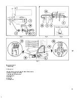
(Fig. 2)
The slots of the burner must be centrally located under the boiler
tube.
See “Periodic maintenance”.
The Flame Failure Safety Device
(Fig. 3)
The feeler of the thermo couple shall reach in over two slots of
the burner. To replace the thermo couple proceed as follows:
1. Unscrew plug 23 and holder 22 and pull thermo-couple
straight out.
2. Remove holder 24.
3. Pull out holder sideways from burner housing.
4. Bend the new thermocouple to the same shape as the old
one.
5. Reassemble in reverse order. Check that feeler has been
correctly refitted in relation to burner. See Fig. 4.
6. Mount holder. The plug must be properly tightened to the
valve housing to ensure good contact between the thermo-
couple and the magnetic coil within the housing.
The Thermostat
(knob B)
The refrigerator is equipped with a thermostat which is regulated
by turning the knob to different settings in order to obtain the
desired controlled cabinet temperature.
With the dial l-7 various controlled temperatures can be
obtained, the higher the number, the lower the temperature.
As soon as the required cold temperature inside the cabinet is
reached, the thermostat cuts the burner.
At MAX The burner is running continuously at full gas rate. Low-
est cabinet and freezer temperatures are obtained at
this setting.
ELECTRIC EQUIPMENT
Cartridge heater
The refrigerator is equipped also for electric operation. These
models are equipped for both 120 Volts A C and 12 Volts DC
operation.
The heat necessary for the operation of an absorption type cool-
ing unit is supplied by an electric cartridge heater mounted in a
pocket of the boiler system.
To replace the heater first of course check that the wall plug is
disconnected. Also make sure that the 12 V leads are discon-
nected. Then proceed as follows, see fig. 5:
1. Push the metal hose upwards
2. Disconnect the heater connector
3. With a pair of pliers unfold the lug holding the lid of the boiler
casing and open the lid
4. Remove some insulation wool so that the heater is accessible.
5. Turn and lift the heater out of its pocket
6. Fit the new heater into the pocket
7. Connect the leads and pull on the hose around the leads
8. Reset the insulation and close the lid of the boiler casing.
PERIODIC MAINTENANCE
NOTE. Before working on the refrigerator make sure that 120 V
A.C. and 12 VD.C. leads are disconnected.
The Burner and the Burner Jet
(Fig. 2)
The colour of the flame shall be clear blue over the slots of the
burner (Fig. 4).
Once or twice a year depending on use, it is necessary to clean
and adjust the burner assembly. Proceed as follows:
1. Loosen screw and remove cover plate for burner housing.
2. Disconnect lighter cable from the electrode.
3. Loosen burner fixing screw and withdraw burner.
4. Clean burner tube with a brush. Blow with compressed air.
5. Screw off jet and clean with alcohol. Blow with compressed
air. Never use a needle or similar.
6. Reassemble.
The Electrode
For a proper ignition function it is necessary to keep the electrode
insulation dry and free from dirt. The gap between burner tube
and electrode shall be max.
3/16"
(5 mm) and min. 1/8" (3 mm).
WARNING
If the refrigerator is used intermittently it should be checked at
least once a year.
It is important to keep the appliance area clear and free from
combustible materials, gasoline and other flammable vapors
and liquides. Check the venting system. The flow of combustion
and ventilating air must not be obstructed.
Check the flue baffle that it is clean and reasonably free from
soot. Heavy soot formation indicates improper functioning of the
burner. Clean baffle and flue. Further, clean cooling unit and floor
under refrigerator.
The entire gas installation should be checked for leaks at inter-
vals. Test all pipe connections with soapy water, not with an open
flame.
Check the energy selector system by connecting/disconnecting
main voltage, start/stop the engine etc.
Compare and check that the system behaves as it is described
on p. 7 above. If in doubt please contact a service center.
NOTE.
Any service of the gas controls, with exception for the
above mentloned replacement, maintenance and cleaning
operations must be performed by an authorized service
center only.
8
Содержание RM663 and
Страница 2: ...0 10 Fig 1 0 1 ...

