background image


16

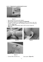
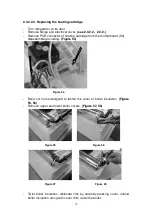
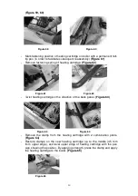
-  When ready with the operation, clip back the lighting panel in its place, and 

order the cables. 

-  Place  light  cover  in  grooves  located  in  internal  container,  clip  on,  and


tighten light cover screws.

 (Figure 42) 


After disassembling this electrical part, no electrical insulation resistance test 
is necessary. 
After  assembling,  connect  the  appliance  to  the  electrical  supply,  and  check 
operation through the self-test of the electronics. 

(see 2. 3. 1. 2.)


2.3.2.2. Checking and replacing parts connected to the Fuzzy controller 
 

These parts can be made available as follows: 
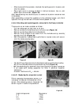
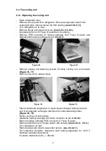
-  Turn the refrigerator so that it lies on its door 
-  Remove screws from electrical cover, remove cover 

(Figure 43)


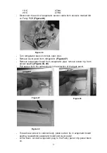
-  Remove connecting cables from motherboard. 
-  Remove  Fuzzy  printed  circuit  board  from  the  motherboard  by  carefully 

pressing the horns.

 (Figure 44)


-  After the operation, reassembly is performed in reverse order, with care to 

order the cables appropriately. 

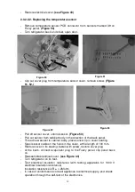
-  Clip back Fuzzy III panel to the motherboard, taking care that the locating 

peg of the motherboard fits the panel fastening hole.

 (Figure 45)


-  After disassembling the electrical circuit, test electrical insulation resistance 

in  all  cases  (with  testing  apparatus  for  1000  V  electrical  insulation 
resistance).  
Insulation resistance is R

ins

 > 2Mohm 


2.3.2.2.1. Replacing the evaporator sensor 


Prior to replacing the evaporator sensor, it is 
necessary to measure the resistance of the 
sensor. If the following value is measured, the 
sensor is good, it needs no replacement. 


Interior temperature  


Resistance 


0 °C   


15.5


5°C 


19.8


10°C   


26.2


Figure 45 

Figure 43 

Figure 44 

Содержание RH 449LD

Страница 1: ...1 Service Instructions RH423LDA RH423LDAG RH439LDA RH439LDAG RH449LD RH439D RH449D Freestanding and built in absorption refrigerators...

Страница 2: ...3 1 2 Self test 12 2 3 1 3 Defrost 12 2 3 1 4 Checking the cooling unit CUC 13 2 3 1 5 Checking the Automatic Door Control optional function 13 2 3 1 6 Temperature control 13 2 3 2 Assembly 14 2 3 2 1...

Страница 3: ...ate the appliance in accordance with the operating manual Any repairs that involve the disassembly of electrical parts should only be performed by an authorized service person Certain parts of the coo...

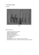
Страница 4: ...er handgrip screwdriver bit marked Pz 1 screwdriver bit marked Pz 2 crosshead screwdriver marked Ph 1 flat screwdriver 120 5 flat screwdriver 100 4 spanner size 14 testing apparatus for 1000 V electri...

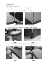
Страница 5: ...door hinge Figure 2 Remove the screws of the upper door hinge cover cap Figure 3 Open the door pull out the upper door hinge by tilting the door Figure 4 Put aside the door hinge unhook door from lowe...

Страница 6: ...with the refrigerator into upper left door hinge hole on door restore plastic cover and fasten with 2 screws Figure 10 11 Restore door hinge cover cap to upper right aperture then fasten with screw F...

Страница 7: ...iances that are fitted with only fastening feet The size of such foot at the back is naturally smaller Remove cables of red dot from the fastening feet where applicable Figure 16 2 2 2 2 Rear feet Rem...

Страница 8: ...ile the rest of the screws need only loosening in order that the cowl can be slid from under the screw Figure 22 Remove cowl then restore the replacement part by sliding it under the screws Figure 23...

Страница 9: ...r With the bolt contracted pull the rim of the lock cover onto the bolt with the help of a flat screwdriver so that it will not spring back Figure 25 Remove lock cover with the help of 2 flat screwdri...

Страница 10: ...eplacement of the door panel must be performed when the door and lock are disassembled see sections 2 2 1 and 2 2 4 Remove door shelves Removing these may be performed by lifting the shelves Figure 29...

Страница 11: ...el in the grooves in the door Push the panel to an extent that the holes of the cylinder lock on the panel and the door are concentric Figure 34 Insert frame edge fasten with screws Reassemble lock se...

Страница 12: ...e performed manually 2 3 1 2 Self test The built in electronics execute a self test when voltage is applied to the appliance The system checks the condition of peripheral devices The result is indicat...

Страница 13: ...ket for more than 10 seconds 2 3 1 5 Checking the Automatic Door Control optional function The red LED is normally placed in the right side foot of the miniBar normally opens to the right When the LED...

Страница 14: ...Remove the cover fastening screw set aside the bolts only for appliance fitted with lock Figure 35 Remove light cover by carefully pulling it with two screwdrivers Figure 36 Remove the light panel by...

Страница 15: ...39 By carefully pressing the hemispherical ends of the sensor parts with fingertips push the sensor from its seating hold onto it at the wires and remove it Figure 40 Apply new sensor to the seating f...

Страница 16: ...ting cables from motherboard Remove Fuzzy printed circuit board from the motherboard by carefully pressing the horns Figure 44 After the operation reassembly is performed in reverse order with care to...

Страница 17: ...47 Remove evaporator board from evaporator pipe remove sensor tip from sensor seating Figure 48 49 Pull sensor from the cabinet body in the direction of the back panel Thread new sensor to cabinet bod...

Страница 18: ...y place sensor tip in cover seating Spool sensor cable on the horns in the cover at the length of 100 mm Restore cover in its seating fasten with screw restore cover plug At the back connect evaporato...

Страница 19: ...ge from the motherboard X3 disassemble grounding Figure 54 Bend out horns designed to fasten the cover of boiler insulation Figure 55 56 Remove upper and lower boiler covers Figure 57 58 Twist boiler...

Страница 20: ...irection of the back panel Figure 63 Remove the clamp from the heating cartridge with 2 combination pliers Figure 64 Restore clamps on the new heating cartridge up to the middle 45 mm from upper edge...

Страница 21: ...bending horns on cover Figure 67 68 69 Thread the fastening ring of heating cartridge cable to the cartridge cable clip spring on liquid heat exchanger Figure 70 Restore PCB connector to motherboard c...

Страница 22: ...Remove LED cable from fastening foot groove restoring new cable Figure 75 Screwing on fastening foot and foot extension Order LED cable on bottom panel and fasten in cable fastener Connect PCB plug t...

Страница 23: ...cooling unit and isolate Figure 76 77 Restore new unit to cabinet body Place condensate evaporator on liquid heat exchanger taking care that end of condensate outlet pipe reaches the condensate evapo...

Страница 24: ...4 2 5 Information Certain appliance versions do not contain all parts lock flange automatic door control light Sections of the instructions relevant to the above do not apply to such appliance version...

Отзывы: