background image

6

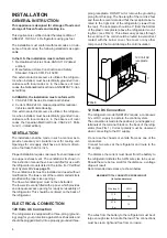
Step 2: Two screws installed in the top frame.

The top decoration panel must be removed from the re-
frigerator before the screws can be installed.

Open the doors and remove the four screws that secure
the top decoration panel to the top frame. Two screws
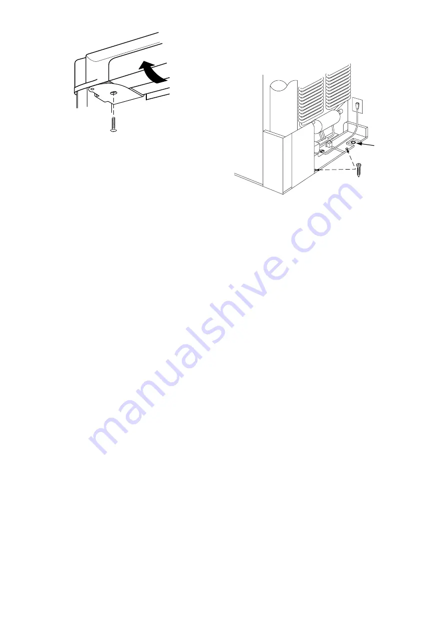
are accessible from underneath see FIG. 7, the second
two screws that secure the decoration panel to the front
frame are located on each side of the lock retainer.
Carefully tilt the top decoration panel and lift up to re-
move from top frame. Be careful not to damage the cir-
cuit board and wires.
Install the two screws in the top frame, the holes are
accessible from underneath.
Seal the opening for the screws with aluminum tape.
Replace the top decoration panel with its four screws.
Be careful not to pinch the wires behind the panel.

Failure to follow the sequence in securing refrigerator in
enclosure can cause leakage between the frame and
cabinet.
Any space between the counter, storage area or ceiling
and top of the refrigerator greater den 1-1/2 inches should
be blocked. The heat produced at the rear of the refrig-
erator will become trapped in this space, making the top
of the refrigerator hot and reduce the efficiency of the
refrigerator.

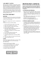
Drain water hose

A hole must be drilled through flooring see FIG. 8.
The hole must be drilled in the cut out opening of the
base plate at the rear of the refrigerator. The installer
MUST make sure that the hose does not kink when run
through the floor. Seal around the hose that goes through
the drilled hole. If a longer hose than supplied is required
to get the water to drain outside of the vehicle, the in-
staller will have to supply the extra length of hose.

STEP 3: Two screws installed in the rear base.

See FIG. 8.

FIG. 7

Hole for drain
water hose

FIG. 8

Содержание NDE1292

Страница 1: ...y of this or any other appliance WARNING Improper installation adjustment alteration service or maintenance can cause injury or property damage Refer to this manual For assistance or additional inform...

Страница 2: ......

Страница 3: ...e Protection cover Power module and fuses Heaters Refrigerator control panel FIG 2 AC OFF ON COLD 1 2 3 4 5 COLDEST 1 2 B A C D LEGEND 1 Main Power Button ON OFF 2 Temperature Selector Button A AC Ind...

Страница 4: ...ize openings The flow of ventilating air must not be obstructed The lower side vent is fitted with a panel which provides an adequate access opening for ready serviceability of the refrigerator This s...

Страница 5: ...xtends at least full width and depth of the appliance Caution Use care when installing the refrigerator This refrigerator is equipped with the latest vacuum insulated panel technology These insulating...

Страница 6: ...the panel Failure to follow the sequence in securing refrigerator in enclosure can cause leakage between the frame and cabinet Any space between the counter storage area or ceiling and top of the ref...

Страница 7: ...ondenser coil at the back of the refrigerator VENTILATION HEIGHTS CLEARANCES Minimum clearances in inches to combustible materials are G Top 0 K Side 0 L Bottom 0 M Rear 0 N See NOTE Clearance N below...

Страница 8: ...f hydrogen and ammonia gas or in severe cases completely block it resulting in a loss of cooling Any time the vehicle is parked for several hours with the refrigerator operating the vehicle should be...

Страница 9: ...e or associated electronic circuitry occurs If this should occur the re frigerator will run continuously The refrigerator will continue to operate in this mode in definitely or until a new sensor is i...

Страница 10: ...he refrigerator by pressing the main power ON OFF button to the UP OFF position Empty the refrigerator leaving the drip tray under the finned evaporator and the cabinet and freezer doors open Filling...

Страница 11: ...r the refrig erator control system and one for the AC heater See table below To replace fuse s proceed as follows 1 Disconnect the wall plug and the 12 volt wires 2 Remove the power module cover See F...

Страница 12: ...ose given in the Table on this page and the instructions are read thoroughly When mounting the panel proceed as follows See figure page 13 A Open the door 90 degrees On new refrigerators the decoratio...

Страница 13: ...03633 XXX Roof Cover 3103634 XXX Lower Side Vent 3109349 XXX Power Vent Asm 3108705 744 Fill in XXX with color code numbers For color codes contact your supplier Alternate instructions forwarded with...

Страница 14: ...side at the desired position Slide the wire shelf to the left The right hand side of the shelf will come loose Slide the shelf into the holes on the right hand side Lower the right hand side of the wi...

Страница 15: ...15...

Страница 16: ...16 MO FO 0424...

Отзывы: