
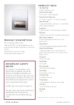
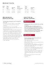


PRODUCT DATA
Input Motor Heater Total
VAC Inrush Operating Inrush/ Inrush Operating
A(W) A(W) Operating A(W) A(W) A(W)
220 2.86 (630) 1.91 (420) 1.91 (420) 4.77 (1050) 3.82 (840)
230 2.99 (689) 2.00 (459) 2.00 (459) 4.99 (1148) 3.99 (918)
240 3.13 (750) 2.08 (500) 2.08 (500) 5.21 (1250) 4.17 (1000)
MECHANICAL
INSTALLATION:
›
Recommended wall opening for proud mounting: 360w x
431h x 112d
›
Position the unit into the prepared wall recess allowing a
6mm clearance all around the unit for packing and
adjustment.
›
Open door panel of dryer using key provided.
›
Remove and retain 2 cover screws from underside of internal
dryer casing, remove casing.
›
Provide supply wire in accordance to local wiring regulations
to hole location in rear of back box and attach securely to
chassis with suitable cable gland (May differ to that supplied)
›
Fit temporary screws into slots on side walls. Do not fully
tighten screws into wall to allow for horizontal adjustment.
›
Fix casing to surrounding structure using suitable screws. Pack
and adjust as necessary to ensure unit is square and level. Do
not over tighten screws or the unit casing may become
distorted. Remove temporary screws from slots.
›
Re-fit internal dryer casing and re-fit retained screws.
›
Close and lock door
ELECTRICAL
INSTALLATION:
s
WARNING
›
Disconnect power at the service breaker before installation
or servicing
›
A qualified electrician must install this product. It is
recommended that this unit be checked every 6 months
›
All units must be supplied with a 3-wire service. The earth
wire must be connected to the dryer’s back plate
›
The means of disconnection must be in the fixed wiring in
accordance with the correct electrical regulations
s
DANGER
›
Failure to properly ground unit could result in severe
electrical shock and/or death.
›
Open door panel with suction cup provided.
Door is right hand hinged.
›
Remove and retain 2 cover screws from underside of internal
dryer casing, remove casing
›
Provide supply wire in accordance to local wiring regulations
through suitable cable gland (May differ to that supplied) in
rear and attach securely to chassis
›
The hand dryer must be supplied from the mains (220-240
volt supply) via a suitably rated double pole isolation switch
with at least 3mm air gap in each pole.
›
Connect supply and ground wires to terminal block where
indicated or connect supply wires to terminal block where
indicated and connect ground wire to base with ground
screw
›
Re-fit internal dryer casing and re-fit retained screws
(Do not overtighten)
›
Close door
!
!
3
02.4011 User Manual
www.dolphinsolutions.co.uk


