24
UH 5947 / 25.03.19 en / 091A
Response time up to the cut-out process after expiration of the set start-
up delay time
The max. response time up to the detection of an underfrequency condi-
tion depends on the threshold to be checked. The max. response time up
to the detection of an overfrequency condition depends on the present
measuring signal. The lower the set threshold the more time needs the
device to detect the failure. To achieve a quicker response time encoders
or gearwheels may be used which deliver more pulses per revolution (e.g.
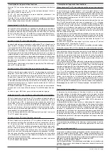
encoders with line number 32). This reduces the time 1/f
Threshold
by the fac-
tor that equals to the encoder’s number of lines or number of teeth.
General rule:
Example: Underspeed to be monitored in setup mode 120 rpm = 2 Hz
With prox. sens.:
(1 pulse/rev.)
With encoder with
number of lines = 32:
f
= set frequency threshold or frequency of the
present measuring signal
(e.g. underfrequency in setup mode)
t
response
= internal response time after detection of
cut-out frequency (max. 150 ms)
Display
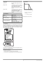
In normal operating mode, all settings can be checked at any time by
pressing the UP or DOWN keys.
Additionally, the current speed from proximity sensor 1 or from the encod-
er is displayed. However, this speed does not correspond to the device’s
accuracy and is only designed for diagnostic purposes.
In the case of wiring errors and system failures corresponding diagnostic
messages are displayed on the display unless they are deliberately disa-
bled in the parameterization.
Parameterization
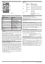
Parameterization and pin assignment of the RJ45 interface
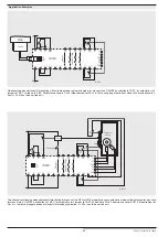
When the UH 5947 is appropriately configured, the RJ45 interface is used
to connect an encoder to the device. All 4 signal paths (A, A, B, B) and
GND must be connected with the Encoder.
Moreover, this interface can be used to parameterize another device us-
ing an appropriate transfer cable OA 5947/100 (see accessories) and the
copy function. This is useful when the speed monitor is to be used in a
serial application or has to be replaced in case of failure.
cos (B)
RJ45
Pin 8
Pin 7
Pin 6
Pin 5
Pin 4
Pin 3
Pin 2
Pin 1
TxD
cos (B)
RxD
sin (A)
sin (A)
GND
M9799_a
Parameterization using the display
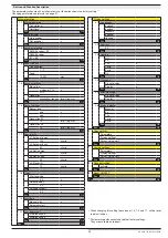
See attached form page 57
Change tracking
To detect non permitted changes of the settings, the menue item change
tracking is available. This setting allows to activate a counter once, which
is then incremented with each confirmed change of the settings. After ac-
tivation of this function the user cannot reset the counter or disable this
function again.
t
response_max
=
+ t
Reaktion
1
f
t
response_max
=
+ 150 ms = 650 ms
1
2 Hz
t
response_max
=
+ 150 ms = 166 ms
1
2 Hz x 32
Device and Function Description
Содержание SAFEMASTER S UH 5947
Страница 4: ...4 UH 5947 25 03 19 de 091A ...
Страница 20: ...20 UH 5947 25 03 19 en 091A ...
Страница 36: ...36 UH 5947 25 03 19 fr 091A ...
Страница 54: ...54 UH 5947 25 03 19 de en fr 091A ...


