


EN - DOL 25 SENSOR TECHNI
CAL USER’S GUIDE
INSTALLATION GUIDE
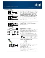
Figure 4
PNP (Figure 4)/NPN (Figure 5) electric installation:
Connect the sensor to a DC supply and connect the loads
between the outputs and V- for the PNP version and V+
for the NPN version. The sensor is protected against
polarity errors, and the outputs are protected against
overload and short circuit. If the output current exceeds
the nominal output current, the output function is
switched off. Eliminate the short circuit or choose a
smaller load to eliminate the error. The current limitation
error is indicated on the sensor by two quick flashes
followed by a pause.
Figure 5
NC
Figure 6
SCR (Figure 6) electric installation:
The sensor is connected in series with the load. The
polarity is unimportant.
Figure 7
Functional description, Figure 7:
When material is in front of the sensor, the NO output is
ON and the NC output is OFF. When the material
disappears the timer will start, and after OFF time delay
the outputs will change condition.
Status on the sensor is indicated by an orange LED.
Sensor
NO-contact
NC-contact
LED
OFF
ON
OFF
ON
OFF
ON
ON
OFF
Flashing
Figure 8
The sensor can be supplied with either
• no setting
• one setting
• two settings
Setting of sensivitity, Figure 8:
The sensitivity is reduced by turning the potentiometer
counter-clockwise and increased by turning the
potentiometer clockwise.
Setting of time delay, Figure 8:
The time delay is reduced by turning the potentiometer
counter-clockwise and increased by turning the
potentiometer clockwise.
LED
Sensor
Output on
Output off
Output on
Output off
Ti
m
e
d
elay
S
en
siti
v
ity
On
Off
NC
NO
NC
NO
(Make)
(Break)
90-250 V AC
50-60 Hz
10-36 V DC
10-36 V DC