


2
9800 Series Keypad Installation Guide
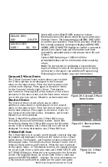
Select Areas
There are four Select Areas in the display as
seen in Figure 2. These Select Areas are one of
the features that make the system so easy to
operate. They allow you to make selections by
pressing the area over each key, icon, or other
selection to operate the keypad.
Warning:
DO NOT use any sharp objects to
operate the touchscreen such as a pen or
pencil.
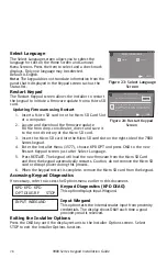
Panic Icons
Optional Panic functions allow users to send
Police, Emergency, or Fire reports to the central station as seen in Figure 3. You must
enable the Panic function in Installer Options in order to use the Panic Icons. See
Programming Keypad Options later in this document.
Press the panic icon in the carousel menu to bring up the Panic Options menu. This
icon can be seen in Figure 4. Press the panic menu icon for 2 seconds until a beep
is heard. At the beep, the panel sends the following zone alarm reports to the
central station:
Panic
- Zone 19 + Device Address
Emergency
- non-medical - Zone 29 + Device Address
Fire
- Zone 39 + Device Address
Keypad Backlighting
The touchscreen illuminates at the maximum brightness any time the display is
pressed. During an alarm condition, the touchscreen turns Red. When all alarm
conditions are cleared, the user-selected brightness is restored.
Cleaning the Touchscreen Display
To minimize unintended key presses, select the keypad option from the main carousel
menu and clean the touchscreen using a water dampened soft, lint-free cloth. Apply
the water onto the cloth, do NOT apply directly onto the touchscreen. After cleaning,
wipe the touchscreen dry with a soft, lint-free cloth. Touch the blue mini shield that
displays in the upper left corner to return to the Main Screen.
Figure 2: Touchscreen Select Areas
1
ABC
5
MNO
9
YZ
2
DEF
6
PQR
0
3
GHI
7
STU
4
JKL
8
VWX
CMD
Select Area 1 Select Area 2 Select Area 3 Select Area 4
Figure 3 and Figure 4: Graphic Keypad Panic Icons
DISARMED
NOW
TUE
Panic
Chime
Check-in
Reset
MONITOR ON
PANIC OPTIONS
PRESS AND HOLD BUTTON TO SEND
FIRE
POLICE
EMERGENCY
Содержание 9800 Series
Страница 23: ...9800 Series Keypad Installation Guide 21 ...