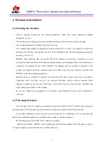
background image

DMEGC Photovoltaic Modules Installation Manual

- 11 -

5. Electrical Installation

Any hardware used must be compatible with any other used material to avoid galvanic corrosion.
Defects caused by corrosions void the warranty.

It is not recommended to use modules with different configurations (grounding, wiring) in the same
system.

Excessive cables must be organized or fixed in an adequate way, e.g. attached to the mounting
structure by using non-metallic cable ties. Solar cables, connectors and junction boxes should not be
exposed to water exposure, and snow, and rain or water submersion for a long period of
time(IP65/67/68).

For applications requiring high operating voltage several modules can be connected in series to form a
string of modules; the system voltage is then equal to the sum of the voltage of each module.

For applications requiring high operating currents several strings of modules can be connected in
parallel; the system current is then equal to the sum of the current of each string of modules.

The maximum system voltage is 600 volts ,1000 volts or 1500 volts depending on the product family
DC according to standards.

The maximum number of series connected modules depends on system design, the type of inverter
used and environmental conditions.

Based on the maximum series fuse rating of module and local electrical installation code, always make
sure DMEGC PV modules are assembled with the appropriate string fuse for circuit protection.
There is no specific limitation on the number of modules that can be connected in parallel, the number
of modules is determined by system design parameters such as current or power output.

To prevent the cables and the connectors from overheating, the cross section of the cables and the
capacity of the connectors must be selected to suit the maximum system short circuit current. The
recommended cable is PV wire with a cross section of at least 4mm

2

.

Caution: do not secure the cables too tight. Any cable damage caused by cable management system
is not covered under DMEGC’s warranty.

Always refer to the cable manufacturer's bending radius which includes the radius just behind the
connectors.

When designing large modules arrays connected to a single inverter, always take into account the
resulting isolation resistance (Riso), which decrease increasing the number of modules in the array. A
too low Riso can results in inverter faults. Please refer to local regulations to determine the system
wires size, type and temperature.

Содержание DM M2-60BW Series

Страница 1: ...agnetics Co Ltd DMEGC Solar Energy Hengdian Industrial Area Dongyang City Zhejiang Province China Tel 86 579 86554950 Fax 86 579 86554845 Email solar dmegc com cn DMEGC Photovoltaic Modules Installati...

Страница 2: ...RE SAFETY 4 3 PRODUCT IDENTIFICATION 4 4 MECHANICAL INSTALLATION 5 4 1 SELECTING THE LOCATION 5 4 2 TILT ANGLE SELECTION 5 4 3 CONVENTIONAL REQUIREMENTS 6 4 4 INSTALLATION METHODS 7 4 5 ATTACHMENT GUI...

Страница 3: ...30 applocation class A Modules rated for use in this applications class may be used in system operating at greater than 50V DC or 240W where general contact access is anticlpated Modules qualified for...

Страница 4: ...they are ready to be installed Store pallets in a ventilated rain proof and dry location until the Modules are ready to be unpacked During the transportation do not to apply direct pressure on the bac...

Страница 5: ...module unnecessarily during installation The glass surface and the frame may be hot there is a risk of burns and electric shock Do not work in the rain snow or in windy conditions Avoid exposing cabl...

Страница 6: ...heet and the mounting surface Roof construction and installation may affect the fire safety of the building Improper installation may create hazards in the event of a fire Use appropriate components s...

Страница 7: ...he coastline Confirm with DMEGC install after obtaining approval Modules must be installed or operated in areas where salt hail snow sand dust air pollution chemically active acid rain soot etc are ex...

Страница 8: ...is 2900 PSI 20 Mpa in order to avoid potential damages to module frames Follow the instruction of the clamping system supplier Provide adequate ventilation under the modules in conformity to your loc...

Страница 9: ...e suggest stainless steel M8 bolts should be around 15 20 N m the mounting details are shown in the following figures 4 4 2 Mounting with Clamps When choosing this type of clamp mounting method use at...

Страница 10: ...eet a maximum positive pressure of 1600Pa and negative pressure of 1600 Pa this design load was then tested with a safety factor of 1 5 times The high loading capacity applies to severe environment li...

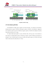
Страница 11: ...DMEGC Photovoltaic Modules Installation Manual 9 4 5 1Framed module bolt and clamp installation...

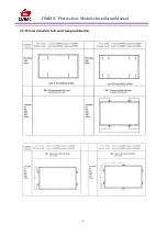
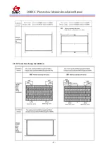
Страница 12: ...DMEGC Photovoltaic Modules Installation Manual 10 4 5 2 Frameless clamp installation...

Страница 13: ...mum number of series connected modules depends on system design the type of inverter used and environmental conditions Based on the maximum series fuse rating of module and local electrical installati...

Страница 14: ...l utility are generally required Especially for larger installations DMEGC recommends lightning protection following the local requirements and regulations 6 Grounding For grounding and bonding requir...

Страница 15: ...381 are used with metal framed photovoltaic solar panels and related products that require grounding for safety reasons 3 Addition Third party Grounding Devices DMEGC PV Modules can be grounded using...

Страница 16: ...ater and a soft sponge or cloth for cleaning A mild nonabrasive cleaning agent can be used to remove stubborn dirt In order to reduce the potential for electrical and thermal shock DMEGC recommends cl...

Страница 17: ...out of or in any way connected with such installation operation use or maintenance No responsibility is assumed by DMEGC for any infringement of patents or other rights of third parties which may res...

Страница 18: ...xxxB6 60NT DMGxxxB6 60NT DMxxxM2 B60NT DMxxxM2 B60NT Group 5 72 156 75 cells modules with aluminium frame xxx 355 370 in increment of 5 DMGxxxM6 72BT DMGxxxM6 72BW DMGxxxM6 72ST DMGxxxM6 72SW DMGxxxM6...

Страница 19: ...DMxxxM2 B72HBT DMxxxM2 B72HSW DMxxxM2 B72HBW Group 11 120 166 cells modules with aluminium frame xxx 355 375 in increment of 5 DMxxxM6 G60HST DMGxxxM6 G60HBT DMxxxM6 G60HSW DMxxxM6 G60HBW Group 12 120...

Отзывы: