


DMEGC Photovoltaic Modules Installation Manual
- 6 -
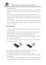
4.3 conventional requirements
The module mounting structure must be made of durable, corrosion-resistant and UV-resistant
material. Always use a tested and certified mounting structure approved for your system design.
Ensure the installation method and supporting system of modules is strong enough to withstand all the
load conditions. Always observe the instructions and safety precautions included with the module
support frames.
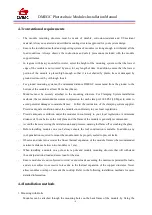
In regions with heavy snowfall in winter, select the height of the mounting system so that the lowest
edge of the module is not covered by snow for any length of time. In addition, ensure that the lowest
portion of the module is placed high enough so that it is not shaded by plants, trees or damaged by
ground soil moved by or through the air.
For ground mounting systems, the minimum distance DMEGC recommend from the ground to the
bottom of the module is at least 24 inches (60cm).
Modules must be securely attached to the mounting structure. For Clamping System installation
methods, the recommended maximum compression for each clamp is 2900 PSI (20 Mpa) in order to
avoid potential damages to module frames. Follow the instruction of the clamping system supplier.
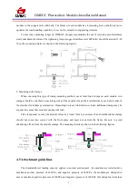
Provide adequate ventilation under the modules in conformity to your local regulations.
Provide adequate ventilation under the modules in conformity to your local regulations. A minimum
distance of 10 cm between the roof plane and the frame of the module is generally recommended.
Avoid the frame receiving the lateral tension and pressure, causing the flame off or crushing the glass.
Before installing modules on a roof, always ensure the roof construction is suitable. In addition, any
roof penetration required to mount the module must be properly sealed to prevent leaks.
Observe and take into account the linear thermal expansion of the module frames (the recommended
minimum distance between two modules is 1 cm).
When installing a module on a pole, select a pole and module mounting structure that will withstand
the anticipated wind load and snow load for the area.
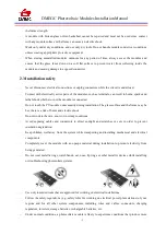
Ensure modules are not subjected to wind or snow loads exceeding the maximum permissible loads,
and are not subject to excessive forces due to the thermal expansion of the support structures. Never
allow modules overlap or exceeds the rooftop: Refer to the following installation methods for more
detailed information.
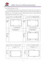
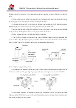
4.4 Installation methods
1. Mounting with Bolts
Modules can be attached through the mounting holes on the back frame of the module, by fixing the