


SuperSigma2 AM PMS
–
V1.5.6 17-1-2020
Page 10 (97)
©2019 DMC GmbH Herten Germany
2
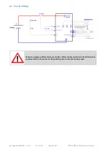
Control Connections
In this section the functions and features associated to each pin of the Ampseal 35 way connector, used for the controller
light wiring will be described in details. The connector ampseal holds the function for interfacing the vehicle, the can
communication and the motor feedback signals. The signals, associated to the pins of the connector, are digital inputs,
analog inputs, communication inputs and digital outputs.
The features associated to the connector signals are different, according to the application software (traction or pump
control). For each pin the specific function, related to the application software, will be described.
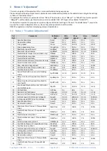
Pins 1-7 are digital inputs. The inputs become active when switched to the ground, if the option active low is selected, or
when connected to the battery plus, if the option active high is selected. (See M3-16T Active
).
Pin 1
Forward i/p -- Pump Potentiometer Switch 1
Traction: Forward i/p
Activating this input in conjunction with the Accelerator Analog Input and the foot switch (if
“
ride on
”
vehicle is
selected - see
Pin 3 Footswitch / Belly Button --
) a drive
forward signal is demanded to the controller.
WARNING!
If both Pin 1 (FW) and Pin 2 (RV) are active at the same time, the controller will detect and signal
the fault with 1 second delay. Please notice that if the vehicle is in neutral and the accelerator is
pressed, if both switched are active at the same time the vehicle will move for 1 second.
Pump: Potentiometer Switch 1
A pump potentiometer can be used to lift the forks on a forklift truck. If the pump potentiometer has a switch, the
switch has to be connected to this input. The programmable parameter
has to be set to 1. Under these conditions, the pump motor will drive if the input is active and the potentiometer
is activated.
Pin 2
Reverse i/p --
Pump Switch 2
Traction: Reverse i/p
Activating this input in conjunction with the Accelerator (
if “ride on” vehicle is selected
-
see “
) a drive reverse operation is activated.
WARNING!
If both Pin 1 (FW) and Pin 2 (RV) are active at the same time, the controller will detect and signal
the fault with 1 second delay. Please notice that if the vehicle is in neutral and the accelerator is
pressed, if both switched are active at the same time the vehicle will move for 1 second.
Pump: Pump Switch 2
Pump Switch 2 is typically related to the forks tilting on a forklift truck.
When activated the pump speed is set to the programmable parameter
.
Pin 3
Footswitch / Belly Button --
Pump Switch 3
Traction: Footswitch / Belly Button
The function of this input can be selected according to the programmable parameter
. If set to Ride (0)
, then the vehicle’s Footswitch should be connected to this pin, and must be
activated
to allow drive. If set to Walkie (1)
, then the vehicle’s Belly Button switch should be connected to this pin. When
the Belly Button switch is closed and the vehicle is running reverse, the vehicle will drive forward in the opposite
direction for 1.5s.
Pump: Pump Switch 3
It is typically used for the lateral shifting of the forks on a forklift truck. When this input is activated the pump
speed is set to the value of the programmable parameter


