background image

Basic safety guidelines 


10 

User’s Manual 

DLoG ITC 7 

Avoid system overloads  

To avoid system overloads, check the sum load of all components installed. 

Make sure that the input current for each consumer falls within the appropriate 
boundaries (see: the technical data for each corresponding consumer). 

2.6.


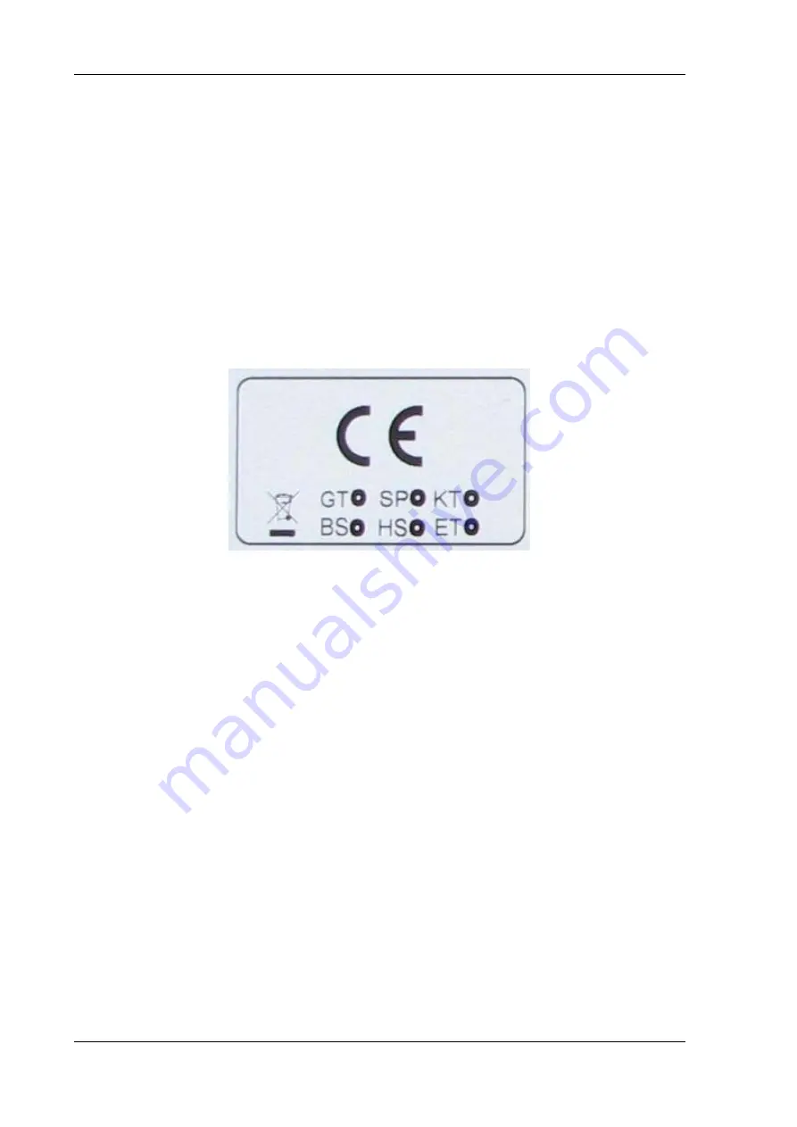
CE Marking 

Warning! This is a class A device. This equipment may cause interference in a residential 
installation. In this case the user is encouraged to perform appropriate measures to 
correct the interference. 


Figure 2.1: CE Marking 


Use care in airplanes or in clinical/medical areas 

Some devices in hospitals and airplanes are not protected from radio frequency 
energy. Consequently, do not use the DLoG ITC 7 in airplanes or hospitals without 
prior authorization. Here use of the DLoG ITC 7 is only permitted if authorization is 
obtained. 

Caution with pacemakers 

Do not use the DLoG ITC 7 near pacemakers. The DLoG ITC 7 can affect the function 
of medically implanted devices such as pacemakers and create interference. Do not 
place the DLoG ITC 7 near such devices.  
Keep a minimum distance of 20 cm between such a device and the DLoG ITC 7 in 
order to reduce the risk of interference.  
If you have reason to assume that interference has occurred, then turn the DLoG ITC 
7 off and consult a heart expert. 

Содержание ITC 7

Страница 1: ...DLoG ITC 7 User s Manual 1 00 ...

Страница 2: ...es caused directly or indirectly by the delivery performance or usage of this material The software and hardware designations used in this documentation are in most cases also registered trademarks and are thus subject to law Windows is a registered trademark of Microsoft Corporation in the United States US and other countries This documentation is protected by copyright Duplication in whole or in...

Страница 3: ......

Страница 4: ......

Страница 5: ...ice 6 2 3 Power supply External peripheral devices 7 2 4 Repairs only through DLoG 8 2 5 Exchanging and extending modules 9 2 6 CE Marking 10 3 Device description 11 3 1 General 11 3 2 Intended usage 11 3 3 Device type plate 12 3 4 Abbreviations used for devices and accessories 13 3 5 Technical specifications 13 3 5 1 Mechanical 13 3 5 2 Motherboard 14 3 5 3 LCD CRT interface 15 3 5 4 Touch screen...

Страница 6: ...ce 22 5 2 Connections in the service lid 23 5 3 Connections under the cable cover 25 5 3 1 DC power supply connections 26 5 4 Connecting external devices 27 5 4 1 Powering down the DLoG ITC 7 27 5 4 2 Powering up the DLoG ITC 7 27 5 5 Removing the protective film 28 5 6 Powering up the DLoG ITC 7 28 5 6 1 Avoid contact with touch screen during booting 28 5 7 Protecting the TFT display from the mem...

Страница 7: ...controls 44 8 2 1 Keys on the front of the device 44 8 2 2 Power key 45 8 2 3 Manual brightness control backlighting 45 8 2 4 LEDs 45 9 Operating system 47 9 1 Pre installed on the hard drive CompactFlash 47 9 2 Installing on the hard drive CompactFlash 48 9 2 1 Operating systems supplied on CD ROM 48 9 2 2 Operating system images 49 9 3 Special features of the operating systems 49 9 3 1 MS DOS 49...

Страница 8: ...port barcode scanners 63 12 6 Tips tricks 64 13 Internal devices 65 13 1 Chipset 65 13 1 1 Installing chipset drivers under MS DOS 65 13 1 2 Installing chipset drivers under MS Windows XP 65 13 2 VGA adapter 67 13 2 1 VGA driver installation under MS DOS 67 13 2 2 VGA driver installation under MS Windows XP 67 13 3 Network adapter 10 100 69 13 3 1 Problems with data transmission via LAN Ethernet 6...

Страница 9: ...ing 73 14 5 Using the touch screen 74 14 6 Use storage in extreme temperatures 74 15 Troubleshooting 75 15 1 COM1 COM2 data transmission 75 15 2 Data transmission via LAN Ethernet 77 16 Maintenance 78 16 1 Cleaning the housing 78 16 2 Touch screen cleaning 78 17 Disposal 78 18 Return packing slip 79 Index 80 ...

Страница 10: ...iew of DC connection plug 26 Figure 5 6 Power supply connection with external power supply 26 Figure 7 1 DLoG ITC 7 with cable cover mounted 35 Figure 7 2 Sealing sleeves 36 Figure 7 3 Cable cover seals 37 Figure 7 4 Separate the sealing sleeves 37 Figure 7 5 Sleeve around a cable 38 Figure 7 6 Strain relief clamps 38 Figure 7 7 Wrong cable layout 39 Figure 7 8 Correct cable layout 39 Figure 7 9 C...

Страница 11: ...2 Welcome screen for the VGA driver installation 68 Figure 13 3 RJ45 network port 69 Figure 13 4 Network driver installation license agreement 70 Figure 13 5 Start screen for network driver installation 71 Figure 13 6 Welcome screen for the onboard sound adapter drivers 72 ...

Страница 12: ......

Страница 13: ...anual carefully and follow all the safety notices listed Follow all basic safety guidelines and the safety notices in the individual chapters Within this manual DLoG GmbH strives to provide all the information required for using your DLoG ITC 7 However because this is a versatile product that can be used in many different scenarios we cannot guarantee that the information contained in this manual ...

Страница 14: ...icates hazards that pose a risk to life and limb such as contacting the power supply The following levels apply denoted by the keywords DANGER WARNING and CAUTION DANGER There is an immediate risk of death serious injury WARNING There is a possible risk of death serious injury CAUTION Mild injury is possible ...

Страница 15: ... symbol indicates hints that help you to understand how to use the product or the manual 1 3 4 Additional design elements Lists are indicated with bullet points for example Cable cover Power pack Instructions are numbered for example 1 Connect the DLoG ITC 7 2 Press POWER key Parameter descriptions e g of a dialog Ignition off This parameter is used to set Delay time This indicates the delay time ...

Страница 16: ...find the command Paste Values Click OK to finish Entries Any text that needs to be entered is shown in Courier font for example 1 Enter the text abcdefg Other methods for emphasis Any other emphasized text elements are highlighted in bold or underlined References to other chapters in the manual are printed in italics ...

Страница 17: ...y operated and maintained incorrectly WARNING Improper use of the unit can lead endanger the user Failure to comply with the safety guidelines can lead to damage to the equipment or even to dangerous injury to personnel The operator commitments in regards to safety accident prevention regulations work protection are to be followed 2 1 Area of application The device is not designed for use in life ...

Страница 18: ... be laid in accordance with the applicable local installation regulations Risk of injury during transit or installation The unit could fall during transit or installation and cause injury Always ensure that there are two persons available when installing or removing the device Supply of fresh air The DLoG ITC 7 is based on a passive cooling concept During passive cooling the waste heat generated i...

Страница 19: ...le or plug is damaged Have the damaged parts replaced immediately Do not connect or disconnect any cables during storms Data cables must never be connected or disconnected during an electrical storm External peripheral devices The use of additional wiring and other peripheral devices which are not recommended or sold by the manufacturer can result in fire electrocution or personal injury If a powe...

Страница 20: ...d send in your unit for repair if necessary On the back of the DLoG ITC 7 you will find the device s type plate which has important information about the device which you must quote for technical service It provides important information about the configuration and manufacture of the device in abbreviated form Always provide technicians with the full model name and serial number ...

Страница 21: ...claims WARNING Using an unsuitable battery type or incorrectly installing it may cause the battery to explode Extending modules When extending or replacing modules only use components approved by DLoG for use in the DLoG ITC 7 Each time before installing a component please contact DLoG to ensure that the desired module can be replaced or installed When extending modules proceed with utmost caution...

Страница 22: ...lanes or in clinical medical areas Some devices in hospitals and airplanes are not protected from radio frequency energy Consequently do not use the DLoG ITC 7 in airplanes or hospitals without prior authorization Here use of the DLoG ITC 7 is only permitted if authorization is obtained Caution with pacemakers Do not use the DLoG ITC 7 near pacemakers The DLoG ITC 7 can affect the function of medi...

Страница 23: ...ons With its 15 touch screen the DLoG ITC 7 is the ideal product for efficient simple work Figure 3 1 DLoG ITC 7 3 2 Intended usage The DLoG ITC 7 is an industrial PC for stationary use in industrial areas for example in production for usage classes see section 7 2 Stationary use only A different or extraordinary usage is not permitted For resulting damage the user operator of the DLoG ITC 7 is so...

Страница 24: ...e DLoG ITC 7 XGA Display resolution e g 12 V with 3 A Input voltage of the power supply with nominal current e g 1 GHz Clock rate of the CPU S N 12 digit serial number composed of DLoG specific device code 37 stands for the DLoG ITC 7 model range Indication of week and year of manufacture Six digits for internal DLoG identification Example of a device type plate Figure 3 2 Device type plate exampl...

Страница 25: ...ave been used Abbreviation Explanation DC DC 3 5 Technical specifications 3 5 1 Mechanical Housing Rugged aluminum cast housing with integrated heat sink Protection class IP 54 ESD safe Weight 6 2 kg Dimensions read section 3 6 Dimensions DLoG ITC 7 Display panel 15 Color TFT XGA 1024 x 768 250 cd m2 DLoG specific resistive Touch Screen Manual brightness adjustment Top Service lid Bottom Cable cov...

Страница 26: ... 44 pin connector 2 mm grid Connectable devices 2 5 hard drives CompactFlash type I II Note for Hard Drives and CompactFlash Cards Only use models approved and released by DLoG to ensure the device functionality Otherwise data loss could increase Enquire which capacities are currently available Floppy disk drive Supports an external 3 5 USB floppy disk drive Protected to ESD level 4 according to E...

Страница 27: ...cted by fuse ESD level 4 protected acc to EN 61000 4 2 Under the service lid Software compatibility MS DOS 6 x MS Windows XP Professional MS Windows XP Embedded 3 5 3 LCD CRT interface VGA controller Integrated Intel Graphics Media Accelerator 900 with up to 224 MByte Dynamic Video Memory Technology DVMT 3 0 Shared memory architecture 3 5 4 Touch screen optional Analog touch controller resistive 1...

Страница 28: ... in accordance with EN 60068 2 1 2 0 C to 50 C Storage temperature Specifications in accordance with EN 60068 2 1 2 0 C to 50 C Relative humidity 10 to 90 40 C non condensating Mechanical vibration and shock resistance Class 5M1 according to DIN EN 60721 3 5 1997 5 hrs with 3 6 g effective noise and 36 vibrations with 30 g peaks Or MIL STD 810F 2000 Department of Defense 3 hrs with 1 g effective n...

Страница 29: ...may only be operated with the AC power supply provided by DLoG Operating the DLoG ITC 7 without the AC power supply provided can irreparably damage the DLoG ITC 7 3 5 9 Maximum power available for peripheral devices The following maximum power may be drawn from the external interfaces of the DLoG ITC 7 USB 2 5 W per interface COM1 and PS 2 a total of 5 W In all the total power drawn may not exceed...

Страница 30: ... User s Manual DLoG ITC 7 3 6 Dimensions DLoG ITC 7 Front view dimensions without add ons in mm Figure 3 3 Dimensions DLoG ITC 7 front view Top view dimensions without add ons in mm Figure 3 4 Dimensions DLoG ITC 7 top view ...

Страница 31: ...Device description DLoG ITC 7 User s Manual 19 Side view dimensions without add ons in mm Figure 3 5 Dimensions DLoG ITC 7 side view ...

Страница 32: ...vice description 20 User s Manual DLoG ITC 7 3 7 VESA drill holes The VESA drill holes on the DLoG ITC 7 are visible on this diagram Dimensions without add ons in mm Figure 3 6 VESA drill holes DLoG ITC 7 ...

Страница 33: ...usly offering the best possible ecological compatibility We therefore kindly request that you store the original packaging material or ensure it is used for another suitable purpose such as transporting the unit or returning shipment If you repack the device please ensure that the cling wrap in the cardboard frame is positioned towards the front of the device so that it can provide the proper prot...

Страница 34: ... sufficient fresh air circulation is required Never install the system in a closed environment where the cooling air is unable to dissipate accumulated heat to the outside Caution Property damage If the DLoG ITC 7 does not have access to fresh cooling air it may result in overheating and severe damage to the unit The maximum permissible ambient temperature for the entire system needs to be taken i...

Страница 35: ... service lid On the upper back of the DLoG ITC 7 there is a service lid Figure 5 1 Service lid closed Inside the service lid there are a service USB interface and a CompactFlash slot Figure 5 2 Service lid open Service lid closed CompactFlash slot Service USB interface ...

Страница 36: ...nnel The service lid may only remain open for the duration of the service work No objects or fluids may be introduced into the service lid Only when the service lid is properly closed again may operation be resumed protection class IP 54 is then ensured again If the DLoG ITC 7 is operated with the service lid for a longer period of time than required for service tasks any warranty claim against DL...

Страница 37: ... Manual 25 5 3 Connections under the cable cover On the back of the DLoG ITC 7 there is a cable cover Figure 5 3 Closed cable cover The connections described below are available here Figure 5 4 External connections under the cable cover ...

Страница 38: ...ply connections Layout Weidmüller SL3 5 2 90F3 2SN 2pol Figure 5 5 Outside view of DC connection plug 5 3 1 1 Power supply cable of the DLoG ITC 7 Power supply connection cable with external power supply Figure 5 6 Power supply connection with external power supply ...

Страница 39: ...ices Make sure that external peripheral devices with their own power supply are switched on at the same time as the DLoG ITC 7 or after you start the DLoG ITC 7 If this is not possible please ensure that the DLoG ITC 7 is adequately protected from power leakage caused by an external device 5 4 1 Powering down the DLoG ITC 7 Always shut down the DLoG ITC 7 as follows 1 Shut down the device properly...

Страница 40: ...eted 5 6 Powering up the DLoG ITC 7 Only power up the DLoG ITC 7 after connecting all of the devices The DLoG ITC 7 is powered up by connecting it to an appropriate power supply and then depending on the version of the device either using the Power switch Caution Property damage Make sure there is a suitable disconnecting device such as a power switch or circuit breaker in the power supply circuit...

Страница 41: ...ularly turning off the display or by using a screensaver with changing content Define in the power management center of the utilized operating system that the displays of the DLoG ITC 7 should be turned off when no user input occurs A motionless image can stay on the display for a maximum of 12 hours After more than 12 hours there is the risk of the memory effect Important for the lifespan of the ...

Страница 42: ...sible to use a PS 2 mouse during Touch operations if you use the touch controller in PS 2 mode By default however the touch controller is operated via COM4 Of course a USB mouse or a RS 232 mouse can always be used in combination with touch mode Resources Resources for the PS 2 mouse controller are pre defined in the system architecture and automatically managed by the BIOS This is also the case f...

Страница 43: ...ly compatible The DVD ROM drive port is provided via USB The drive which is supplied in a separate housing is connected to one of the sockets on the back of the DLoG ITC 7 Depending on the model the external drive is powered either via the DLoG ITC 7 connecting cable or via a separate external power supply If USB has been activated in the BIOS the DVD ROM drive is automatically recognized and made...

Страница 44: ... to the DLoG ITC 7 with a USB A connector 6 5 Scanners Scanners can be connected either via USB PS 2 or a serial interface When connected to COM1 the scanner can be supplied with 5 VDC power through the interface optional Be sure to only use scanners that have been approved by DLoG ...

Страница 45: ...tact your DLoG sales office to find out more about the whole range of installation options on offer WARNING The unit could fall during transit or installation mounting and cause injury Always ensure that there are two persons available when installing or removing the device 7 2 Stationary use only The DLoG ITC 7 is only suitable for stationary use 5 M1 stationary use is defined as follows Operatio...

Страница 46: ...irreparably damage the DLoG ITC 7 The power from the power supply units is designed for operation of a DLoG ITC 7 with normal extension units over the entire operating temperature range There is no switch for the power supply To disconnect the DLoG ITC 7 completely from the power supply network for example pull the power cord out of the AC power supply 7 4 1 Installing connecting cables To connect...

Страница 47: ...and safe working conditions Assembly may only be carried out with the DLoG ITC 7 turned off Before connecting the device cable be sure that no voltage is applied to the cable Please retain these assembly instructions For the cable connection of e g accessories the cable cover must be removed and reattached Be sure to attach the cable cover according to these instructions since the protection class...

Страница 48: ...itions are satisfied during assembly the sealing sleeves provided 1 and 2 figure below are used when installing the cables the unused cable penetrations are closed with dummy sleeves 3 figure below the cable cover is mounted 7 5 1 Preparations Sealing sleeves Figure 7 2 Sealing sleeves 1 size 1 sleeve thin cable 2 size 2 sleeve thick cable 3 dummy sleeve 1 2 3 ...

Страница 49: ...n with dotted lines is present and intact in the cable cover Figure 7 3 Cable cover seals 7 5 2 Cable layout and assembly Pull the plug middle out of the sealing sleeve 1 2 figure below Then separate the sealing sleeve from the outside to the middle 3 figure below 1 2 3 Figure 7 4 Separate the sealing sleeves ...

Страница 50: ...cable Figure 7 5 Sleeve around a cable Instructions for strain relief clamps The figure below show the arrangement for strain relief clamps on the left for a cable diameter CD Ø of 4 mm and up or on the right for a cable diameter Ø of up to 4 mm Figure 7 6 Strain relief clamps ...

Страница 51: ...le layout strain relief Be sure that the cables are not guided straight out of the device Figure 7 7 Wrong cable layout Figure 7 8 Correct cable layout Now place the sleeve and cable into the holder and fasten the outgoing cable with the strain relief clamps ...

Страница 52: ...cables have been mounted the cable cover must be fastened To do this the cable cover must be pressed onto the DLoG ITC 7 housing with the three hooks 1 and then folded downwards 2 Then tighten the three screws on the cable cover with a maximum torque of 0 4 Nm Figure 7 10 Cable cover with three hooks ...

Страница 53: ...Mounting DLoG ITC 7 User s Manual 41 Completely mounted cable cover Figure 7 11 Cable cover mounted ...

Страница 54: ...y closed again may operation be resumed protection class IP 54 is then ensured again If the DLoG ITC 7 is operated with the service lid for a longer period of time than required for service tasks any warranty claim against DLoG GmbH for the device will be void Figure 7 6 DLoG ITC 7 with mounted service lid Take care not to damage the opening seal of the service lid It should be possible to attach ...

Страница 55: ...s will irreparably damage the resistive touch screen Resistive touch screens may NOT be operated with Ball point pens pencils or other inappropriate writing implements Unsuitable touch screen pencils harder than 4 H Hand tools of any kind such as a screwdriver Sharp objects knives scalpels etc that could damage the touch surface 8 1 1 Dirty touch screen surface The surface of the touch screen shou...

Страница 56: ... User s Manual DLoG ITC 7 8 2 Operation controls 8 2 1 Keys on the front of the device The DLoG ITC 7 has the following controls POWER ON OFF Manual brightness control with or LEDs Figure 8 1 DLoG ITC 7 front panel ...

Страница 57: ...r DLoG ITC 7 If the POWER button should be used to shut down the computer this must be configured in the DLoG Config Program Caution data loss may result By activating the POWER button while the computer is in operation the DLoG ITC 7 executes a hard shutdown and there is no controlled shutdown 8 2 3 Manual brightness control backlighting button for manual brightness control button for manual brig...

Страница 58: ...ture in the device is outside of the allowable range Low temperature warning occurs at temperatures of 0 C High temperature warning occurs at temperatures of 70 C The DLoG ITC 7 only starts when the temperature in the device is again within the range of 0 C to 70 C ON OFF The DLoG ITC 7 is either being started or is in normal operation ON ON The DLoG ITC 7 is running and the temperature in the dev...

Страница 59: ...s and touch screens are also pre installed Refer to the relevant operating system manual for specific operating instructions In DLoG ITC 7 units with a pre installed operating system the system is located on the C partition The size of this partition will not always be the same as the size of the entire hard drive CompactFlash It is up to you to organize the usage of the remaining hard drive Compa...

Страница 60: ...Operating systems supplied on CD ROM There are two ways to install operating systems which are supplied on CD ROM Using an external CD or DVD ROM drive connected to a USB port This drive can be used to install for example MS Windows XP SP1 Initialize the hard drive CompactFlash using a bootable floppy disk Then copy the operating system CD and driver CD contents onto the hard drive Compact Flash u...

Страница 61: ...rating system can then be installed from the memory stick Via the network When installing via a network you need to have an external USB floppy disk drive and a bootable disk with the right network driver The operating system image can then be installed from the network server 9 3 Special features of the operating systems Always observe the documentation provided by the operating system s manufact...

Страница 62: ...cessor 486 or higher 80387 Installed Memory 64MB Size of fixed disk 0 1 122MB 1MB DLoG PC model ITC 7 DLoG Serial Number 370002200000A DLoG BIOS Version T7I00C07 Chipset Intel 915 10 2 Fine tuning the operating system parameters The free program TweakUI from Microsoft is used to fine tune the MS Windows user interface Operating parameters that are otherwise inaccessible can be changed with this pr...

Страница 63: ...reted Set whether the DLoG ITC 7 is to constantly monitor the ignition signal during operation Operation Launching MPPCOM EXE h generates the following messages MPCCOM d time0 set power key time time0 time to wait before key press is recognized in 100ms valid values 1 255 MPCCOM h show this help MPCCOM info i readout a lot of info stored in EEPROM MPCCOM p value set power key mode 0 power key comp...

Страница 64: ...while on Accu no Shift key state saved no Backlight key off no keys off no Power key off no Shift key off no Act brightness saved no Use switchoff auto no Wait for powerkey yes Wait for ignition no Switch on device count 70 Powerkey time 2 0s Switch backlight volt 78 Switch on off bkl sw 1 Powerkey sw on count 26 Powerkey sw off count 25 Ignition sw on count 0 Switch off auto count 0 PS ON switch ...

Страница 65: ...the electric circuit is closed and the contact point can be calculated from the voltage differences The touch screen can be operated with or without a keyboard and is compatible with a mouse 11 1 Operation When used improperly for example with sharp objects such as screwdrivers the resistive touch screen will be irreparably damaged Please observe chapter 8 1 Touch screen 11 2 Mouse compatibility I...

Страница 66: ... or optionally the mouse PS 2 port interrupt controlled The driver converts the data into pointer commands The analog touch screen controller used for analysis provides a resolution of 4096 x 4096 pixels 12 bit horizontal and vertical By default the resources for the touch screen controller are the same as for the COM4 port If the appropriate configuration exists these may also be the same as for ...

Страница 67: ...ructions below to install the Hampshire touch screen driver under MS DOS 1 Create the directory C HAMMOUSE This directory name must not be modified 2 Copy the DOS files for the touch screen into this directory These DOS files can be found in the directory C Util on the hard drive Compact Flash of the DLoG ITC 7 or on the driver CD ROM 3 Enter the following command line in the batch file Autoexec b...

Страница 68: ...n also enter the following calling parameters Tx Touch Mode TS Stream TU Pen UP TD Pen Down Sx Touch Sound SN Sound ON SF Sound OFF Cxx Cal Mode C3 3 point C4 4 point C20 20 point V Video Mode VTEXT Calibrate Text mode V640x200 Calibrate 640x200 mode V640x350 Calibrate 640x350 mode V640x480 Calibrate 640x480 mode V800x600 Calibrate 800x600 mode V1024x768 Calibrate 1024x768 Vcustom Calibrate custom...

Страница 69: ... verNR In addition you will find the DLoG drivers on the included driver CD and on the DLoG internet site 1 Open the corresponding folder and run Setup exe 2 On the Welcome dialog click Next 3 Read the Software License Agreement carefully 4 To continue the driver installation you must accept the agreement 5 Then click Next 6 Select Serial RS 232 in the Select Controller dialog box and click Next 7...

Страница 70: ... 4 2 2 Calibration The touch screen must be calibrated so that it functions correctly 1 Start the touch configuration tool under Start Programs Hampshire TSHARC Control Panel 2 Select the Calibration tab and click the Touch field 3 Once calibration is complete finish by clicking Accept 4 Select the Click Settings tab and select Enable right click emulation and enter the following values Right Clic...

Страница 71: ...uch resistive verNR Additionally you will find the DLoG driver on the driver CD supplied with the device and on the DLoG internet site 1 Open the corresponding folder and run Setup exe 2 On the Welcome dialog click Next 3 Read the Software License Agreement carefully 4 To continue the driver installation you must accept the agreement 5 Then click Next 6 On the Select Controller dialog select PS 2 ...

Страница 72: ... the Touch field 3 Once calibration is complete finish by clicking Accept 4 Select the Click Settings tab and select Enable right click emulation and enter the following values Right Click Area Double Click Area each to 13 Right Click Delay Double Click Delay each to the third line 5 Exit the tool with OK 11 5 Right clicking To perform a right click touch the screen and maintain finger contact unt...

Страница 73: ...emicals for a period of one hour at 22 C 45 relative humidity ASTM F 1598 95 Food material Tea Coffee Ketchup Mustard Vinegar Soy Sauce Beer Red Wine Cola Cooking Oil Household and Industrial Chemicals Detergent all purpose cleaner dishwashing detergent glass cleaner hydrogen peroxide 3 Lysol ethanol isopropanol acetone methylethylketone toluene concentrated hydrochloric acid petroleum benzene gas...

Страница 74: ...serial ports are COM1 Address 0x3F8 0x3FF hexadecimal Interrupt IRQ4 COM2 Address 0x2F8 0x2FF hexadecimal Interrupt IRQ3 COM3 Address 0x3E8 0x3EF hexadecimal Interrupt IRQ10 COM4 Address 0x2E8 0x2EF hexadecimal Interrupt IRQ11 12 2 COM1 options The following section describes what needs to be observed when using the COM1 port to supply power to external equipment The resources required for the COM...

Страница 75: ...te that you have to configure the scanner correctly to RS 232 and the above set BAUDrate following the scanner manufacturer s guidelines Otherwise the software wedge will not function properly To activate the integrated scanner software wedge under MS Windows XP Embedded 1 Open the Start menu and navigate to Settings Control Panel Accessibility 2 Select the General tab 3 Select Support accessibili...

Страница 76: ...lfunctions in the RS 232 connections are frequently caused by ground loops If both end devices establish a ground connection via RS 232 but do not share the same ground potential in their power supply circuits then compensation currents may result This is particularly noticeable with long cables These compensation currents which are also present at the ground point of the RS 232 connection may sig...

Страница 77: ... communicate with the system via this chipset Resources The chipset does not require any resources for its core functions unlike the internal peripheral units which are also described in this manual 13 1 1 Installing chipset drivers under MS DOS No drivers are required for MS DOS operation 13 1 2 Installing chipset drivers under MS Windows XP Install the chipset drivers before all other drivers ot...

Страница 78: ...eed as follows to install the chipset driver 1 Open the corresponding folder and run Setup exe Figure 13 1 Welcome screen for chipset driver installation 2 Click Next 3 In the following window click Yes 4 Click Next again 5 Then restart your computer ...

Страница 79: ... VGA adapter is a Plug and Play component for the PCI bus All resource allocation and management is therefore performed by the BIOS 13 2 1 VGA driver installation under MS DOS No drivers are required for MS DOS operation 13 2 2 VGA driver installation under MS Windows XP The graphic card driver to be used can be found by default on the Compact Flash or hard drive under Util vga verNR In addition y...

Страница 80: ...G ITC 7 Proceed as follows to install the VGA driver 1 Open the corresponding folder and run Setup exe Figure 13 2 Welcome screen for the VGA driver installation 2 Click Next 3 In the following window click Yes 4 Now restart your computer ...

Страница 81: ...ED on connected no activity LED on 100 Mbit s network LED flashes connected activity RJ45 network port Figure 13 3 RJ45 network port Resources The network adapter is a true Plug and Play component All resource allocation and management is therefore performed by the BIOS 13 3 1 Problems with data transmission via LAN Ethernet If problems occur during data transmission over LAN Ethernet e g data is ...

Страница 82: ...k drivers to be used can be found by default on the CompactFlash or hard drive under Util Lan verNR In addition you will find the DLoG drivers on the included driver CD Proceed as follows to install the network drivers 1 Open the corresponding folder and run Setup exe Figure 13 4 Network driver installation license agreement 2 Read the Software License Agreement carefully 3 To continue the driver ...

Страница 83: ... ITC 7 User s Manual 71 4 Then click Next 5 Click Next again Figure 13 5 Start screen for network driver installation 6 Now click Install Drivers 7 After the installation click Exit 8 Next the computer needs to be restarted ...

Страница 84: ... BIOS 13 4 1 Installation of the onboard sound adapter drivers Windows XP The sound card drivers to be used can be found by default on the CompactFlash or hard drive under Util Sound verNR In addition you will find the DLoG drivers on the included driver CD Proceed as follows to install the onboard sound adapter drivers 1 Open the corresponding folder and run Setup exe Figure 13 6 Welcome screen f...

Страница 85: ...mounting brackets and screws permitted by DLoG Ensure that ball and socket bases and fastening arms are securely attached Follow the instructions carefully when attaching all outgoing cables to the strain relief rail The service lid may not be used as a handle to turn hold or carry the terminal All fastening brackets and mounting parts supplied by DLoG are only intended for use in the mounting of ...

Страница 86: ...Inappropriate operation of the screen for example by using sharp objects such as screwdrivers will irreparably damage the resistive touch screen Resistive touch screens may NOT be operated with Ball point pens pencils or other inappropriate writing implements Unsuitable touch screen pencils harder than 4 H Hand tools of any kind such as a screwdriver Sharp objects knives scalpels etc that could da...

Страница 87: ...n the menu Advanced CPU Configuration 2 Go to the setting C2 State Support Here Enabled is set by default 3 Change this setting to Disabled The setup line C3 State Support is automatically also set to Disabled 4 Save that BIOS setting and leave the BIOS setup This BIOS setting applies to all COM ports Technical background The changed setting affects the computer s power saving mechanism If the pow...

Страница 88: ...nu and activate Properties 3 Go to Connection settings Advanced 4 Set the Receive buffer and the Transmit buffer to Low 1 5 Confirm this setting with OK This Windows setting must be carried out separately for each COM port unlike the BIOS setup setting Technical background Depending on the application and settings XON XOFF baud rate etc it is helpful in case of transmission problems to activate FI...

Страница 89: ...the Safe mode of the computer when using a Windows start menu e g selecting which operating system should be started when starting the computer in MS DOS mode does not apply to the MS DOS command window in Microsoft Windows when a Windows blue screen error message appears with the request to hit a key when ScanDisk requires input or other messages occur while the PC is booting Fix Use PS 2 devices...

Страница 90: ...lectronics or display 16 2 Touch screen cleaning Clean the resistive touch screen with a clean damp and nonscouring towel and a dishwashing detergent It is recommended to apply the dishwashing detergent onto the towel rather than directly onto the surface of the touch screen Do not use cleaning agents that contain ammonia or sulfur Do not use scouring substances as these could scratch the touch sc...

Страница 91: ...mber Type s of unit s returned Serial number s of the unit s returned The units have not been returned as they are currently being used However the following parts are missing Unit was already damaged on delivery please enclose a copy of the delivery note Delivery was incomplete Missing parts The following error occurs when operating the unit Separate error report is enclosed ...

Страница 92: ... COM4 62 Combination connector 15 Common mistakes in usage 73 CompactFlash capacity 47 CompactFlash slot 23 CompactFlash type I II 14 Compensation currents 64 Compressed air 78 Connecting cables 34 Connecting disconnecting external devices 27 Cooling 22 Cooling air 6 22 Cooling concept 6 Cover for the WiFi card 73 CPU 14 Damaged parts 7 Damaged power cable 7 Data cables 7 Data transmission via LAN...

Страница 93: ...9 MS Windows XP Professional 15 MS Windows XP SP1 48 MS DOS 49 MS DOS 6 x 15 MS DOS operating system 49 Multiple power sources 34 Neck collar screws 42 Network 49 Network adapter 69 Network connection 16 27 Network controller 16 Nominal voltage ranges 34 Onboard sound adapter 72 Opening seal 42 Operating states 46 Operating system 15 47 49 Operating system image 49 Operating system installation 48...

Страница 94: ...h 6 System overloads 10 Technical specifications 13 Temperature in the device 45 Temperature sensor 46 Temperature warning 46 Temperatures on the back 22 Test marks 16 TFT display 29 TN and TT networks 17 Torque 42 Touch controller 15 Touch screen 15 74 Touch screen cleaning 78 Touch screen controller 54 Touch screen pencils 43 74 Touch screen resistive 53 Transmission problems in serial transmiss...

Отзывы: