background image


5.2 Interfaccia display ..................................................................................................... 73 
5.3 Funzione di accensione/spegnimento dell'UPS .............................................. 74 

5.3.1 Procedura di accensione ................................................................................ 74 
5.3.2 Procedura di spegnimento ............................................................................ 74 

5.4 Modalità di funzionamento ................................................................................... 75 
5.5 Richiesta parametri .................................................................................................. 78 
5.6 Impostazioni dell'UPS ............................................................................................. 80 

6. Manutenzione ................................................................................................................. 83 

6.1 Verifica del funzionamento dell'UPS ................................................................... 83 
6.2 Manutenzione dell'UPS .......................................................................................... 83 
6.3 Manutenzione della batteria .................................................................................84 

7. Messaggi di errore e allarmi ........................................................................................ 86 

7.1 Visualizzazione dei guasti ....................................................................................... 86 
7.2 Risoluzione dei problemi........................................................................................ 90 

8. Specifiche tecniche ......................................................................................................... 93 

8.1 Componente elettrica .............................................................................................. 93 
8.2 Durata della batteria................................................................................................94 
8.3 Peso e dimensioni di ingombro ........................................................................... 97 
8.4 Condizioni ambientali ............................................................................................. 97 

9. Garanzia e informazioni di servizio ........................................................................... 98 

Содержание SMALLR1

Страница 1: ...Manuale d uso User s Manual Small Rackmount 1000 3000 Uninterruptible Power Supply Small Rackmount 1000 3000 VA...

Страница 2: ......

Страница 3: ...1 9 2 9 3 10 3 1 10 3 2 10 3 3 11 3 4 11 3 5 12 4 13 4 1 13 4 2 14 4 3 15 4 4 16 4 4 1 16 4 4 2 16 4 4 3 17 4 4 4 17 4 5 17 4 5 1 17 4 5 2 18 4 5 3 18 4 6 19 4 6 1 19 4 6 2 20 4 7 21 4 7 1 21 4 7 2 2...

Страница 4: ...5 25 5 1 25 5 2 27 5 3 29 5 3 1 29 5 3 2 30 5 4 31 5 5 33 5 6 34 6 37 6 1 37 6 2 37 6 3 38 7 39 7 1 40 7 2 45 8 49 8 1 49 8 2 50 8 3 52 8 4 52 8 5 53 9 53...

Страница 5: ...Vista frontale dell UPS 62 4 3 Tipologia 62 4 4 Descrizione del sistema 63 4 4 1 Raddrizzatore 63 4 4 2 Inverter 63 4 4 3 Batterie e caricabatterie 64 4 4 4 Bypass 64 4 5 Stato di funzionamento 64 4 5...

Страница 6: ...ll UPS 80 6 Manutenzione 83 6 1 Verifica del funzionamento dell UPS 83 6 2 Manutenzione dell UPS 83 6 3 Manutenzione della batteria 84 7 Messaggi di errore e allarmi 86 7 1 Visualizzazione dei guasti...

Страница 7: ...5 4 2 Front view of the UPS 107 4 3 Typology 107 4 4 System Description 108 4 4 1 Rectifier 108 4 4 2 Invertor 108 4 4 3 Batteries and Battery Charger 109 4 4 4 Bypass 109 4 5 Operating status 109 4 5...

Страница 8: ...Settings 124 6 Maintenance 127 6 1 Verifying UPS operation 127 6 2 UPS maintenance 127 6 3 Battery maintenance 128 7 Fault Messages and Alarm 130 7 1 Display of faults 130 7 2 Troubleshooting 134 8 Te...

Страница 9: ...7...

Страница 10: ...8...

Страница 11: ...9 1 Small Rackmount 1 Small Rackmount 2 Small Rackmount 3 2 125167 4 8 6 9 7 800 250 52 63 service dkc ru...

Страница 12: ...10 3 3 1 Small Rackmount 3 2 1...

Страница 13: ...11 3 3 1 2 3 1 3 4 3 4 1 2 15 3 4 7...

Страница 14: ...12 3 5...

Страница 15: ...dware SMALLR1A10S I SI H 3 7 1 Schuko IEC Schuko IEC Hardware SMALLR2A0PS I SI H 6 Schuko IEC Schuko IEC Hardware SMALLR2A5S I SI H 4 9 1 Schuko IEC Schuko IEC Hardware SMALLR2A10S I SI H 6 7 1 Schuko...

Страница 16: ...4V SMALLR1 24 BPSMLR1 36V SMALLR1 36 BPSMLR2 48V SMALLR2 48 BPSMLR2 72V SMALLR2 72 BPSMLR3 96V SMALLR3 96 3 2 SMALLR1 1 1 4 1 1 SMALLR2 1 5 1 5 4 1 5 1 5 SMALLR3 2 5 2 5 4 2 5 2 5 4 4 2 1 SMALLR1 SMAL...

Страница 17: ...15 4 3 Small Rackmount IGBT VFI IEC EN62040 1 2...

Страница 18: ...16 2 4 4 4 4 1 4 4 2...

Страница 19: ...17 4 4 3 4 4 4 4 5 3 4 5 1...

Страница 20: ...18 4 5 2 4 5 3...

Страница 21: ...19 4 6 4 6 1 3 SMALLR1 4 SMALLR2 SMALLR3 1 6 RS232 2 7 SNMP AS400 3 8 RJ45 4 USB 9 5 EPO 10 5...

Страница 22: ...20 1 IEC 6 7 2 4 6 2 1 4 1 2 3 5...

Страница 23: ...21 4 7 4 7 1 RS232 USB RS232 1 2 3 4 5 6 7 8 9 USB 1 2 3 4 5V date date GND EPO RS232 2400 8 1 Bit pattern None EPO EPO EPO...

Страница 24: ...22 4 7 2 SNMP AS400 74 66 40 1 2 SNMP AS400 3 SNMP 5 SNMP card SNMP Ethernet IP SNMP...

Страница 25: ...23 TCP IP FTP NTP HTTP SMTP SNMP 1 IP iSearch 2 3 GPRS iSearch USB AS400 AS400 6 AS400 PIN I O PIN1 O P PIN1 PIN5...

Страница 26: ...24 PIN2 O P PIN2 PIN5 PIN3 I P PIN4 I P PIN4 PIN5 PIN5 I P PIN6 O P PIN6 PIN5 PIN7 O P PIN7 PIN5 PIN8 O P PIN8 PIN5 PIN9 O P PIN9 PIN5 6 DB 9 AS400 7 DB 9...

Страница 27: ...25 5 24 D8 D6 D2 D8 D9 D2 D7 D8 D9 D1 D2 D8 K1 K1 7 DB 9 5 5 1 9...

Страница 28: ...26 0 5 0 5 1 1 15 2 2 0 5 2 0 5 2 2...

Страница 29: ...27 2 0 5 2 0 5 2 2 0 5 2 8 5 2 0 25 26 50 51 75 76 100...

Страница 30: ...28 0 25 26 50 51 75 and 76 100 1 2 ECO CUCF 20 20 STDBY BYPASS LINE BAT BATT ECO SHUTDN CUCF...

Страница 31: ...29 ECO LED display 9 5 3 5 3 1 OFF ON ON 0 5 ON 0 5...

Страница 32: ...30 5 3 2 OFF 0 5 BPS ON OFF 7 5 4 2 3 8...

Страница 33: ...31 5 4 ON ON Line...

Страница 34: ...32 bat 4 ECO ECO ECO ECO ECO OFF 10...

Страница 35: ...33 5 5 0 5 2 220 50 800 1 0 v1 7 40 220 50...

Страница 36: ...34 24 100 11 5 6 2 0 5 2 0 5 2 0 5 2 1 2...

Страница 37: ...35 0 5 2 208 220 230 240 9 8 9 9 10 10 2 10 5 50 60...

Страница 38: ...36 ON OFF ECO ECO ON ECO OFF ECO EPO EP EPO ON EPO OFF EPO...

Страница 39: ...37 6 6 1 1 2 3 6 2...

Страница 40: ...38 6 3 1 15 25 C 2 6 3 4 2 5 6 8...

Страница 41: ...39 8 2 30 1 2 3 4 5 6 7 7 7 1 7 2...

Страница 42: ...18 19 Bus 20 21 22 23 24 25 26 27 28 29 30 31 32 33 34 35 36 37 38 39 Bus 40 41 42 43 44 45 46 47 48 49 OP 50 51 52 53 54 55 56 57 58 59 NTC 60 61 62 63 64 65 66 67 68 69 AC 70 71 72 73 74 75 76 77 78...

Страница 43: ...41 LCD 1 Line bAT 4 4 2 bAT 4 4 bAT bAT 3 byPASS 2 4 byPASS bat 0 4 4 Line bat 0 4 4 Line byPASS bat 6...

Страница 44: ...42 5 Line 2 2 FAULT bAT 2 2 FAULT 6 byPASS 2 2 7 2 8 FAULT 13...

Страница 45: ...43 10 0 1 2 3 4 5 6 7 8 9 A B C D E F...

Страница 46: ...44 0 1 2 3 4 5 6 7 8 9 A B C D E F EEPROM Median 0 1 2 3 4 5 6 7...

Страница 47: ...45 8 9 A B C D E F 4 0 1 2 3 4 5 6 7 14 2000 7 2 11...

Страница 48: ...46 00 14 15 24 25 39 40 44 10 45 49 50 54...

Страница 49: ...47 55 59 NTC 60 64 65 69 On 2 3...

Страница 50: ...48 15...

Страница 51: ...49 8 8 1 Small Rackmount 1000 2000 3000 900 1800 2700 208 220 230 240 50 60 110 276 50 100 176 280 280 300 50 40 70 0 99 THDi 6 25 15 200 220 230 240 1 50 60 0 1 0 9 THDu 2 5...

Страница 52: ...50 105 120 1 125 150 30 150 300 0 3 1 90 91 92 85 86 87 ECO 95 96 97 AGM VRLA 24 36 48 72 72 96 1 6 USB RJ45 SNMP 16 8 2 Small Rackmount...

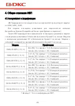
Страница 53: ...51 12 SMALLR1A5 14 SMALLR2A5...

Страница 54: ...SMALLR3A5 8 3 SMALLR1A0 468 440 88 7 6 SMALLR1A5 468 440 88 11 1 SMALLR2A0 468 440 88 9 7 SMALLR2A5 528 440 88 21 4 SMALLR3A0 468 440 88 10 1 SMALLR3A5 560 440 88 30 6 17 8 4 5 C 40 C 25 C 45 C 90 10...

Страница 55: ...53 1000 1000 1500 2000 2500 3000 3500 4000 4500 100 95 91 86 82 78 74 70 19 8 5 004 2011 020 2011 9 2 batt dkc ru service_center...

Страница 56: ...54 8 800 250 52 63 service dkc ru www dkc ru...

Страница 57: ...55 Lingua italiana...

Страница 58: ...56...

Страница 59: ...alsiasi informazione su UPS DKC si prega di contattare DKC EUROPE Srl Via Libert 207 28043 Bellinzago Novarese NO Per assistenza tecnica contattare Numero Verde 800194040 Mail assistenza rambatt dkceu...

Страница 60: ...ackup CD ROM passaporto manuale dell utente 3 2 Descrizione dei simboli principali Fare attenzione ai simboli riportati nella tabella sottostante Simbolo Significato Simbolo Significato Attenzione Mes...

Страница 61: ...za minima dai pannelli anteriore e posteriore 15 cm per garantire una corretta ventilazione 3 Se l UPS stato conservato in un ambiente molto umido o a bassa temperatura necessario attendere fino a qua...

Страница 62: ...compreso tutte le istruzioni contenute nel presente manuale e nella documentazione tecnica di supporto 4 Descrizione generale dell UPS 4 1 Gamma di prodotti e modifiche Ci sono 3 tipi di UPS a second...

Страница 63: ...I H 8 7 h Corrente di carica 1 Prese di uscita Schuko IEC Schuko IEC hardware Tabella 2 Modifiche dell UPS Per aumentare il tempo di autonomia della batteria l utente deve collegare all UPS un armadio...

Страница 64: ...onda del tempo di autonomia della batteria Questa configurazione garantisce il miglior servizio all utente in quanto fornisce energia pulita ininterrottamente assicurando la stabilizzazione di tension...

Страница 65: ...il raddrizzatore la rete di alimentazione non venga distorta rispetto agli altri carichi Ci evita inoltre il surriscaldamento dei cavi dovuto alla circolazione delle armoniche Il raddrizzatore dimens...

Страница 66: ...eversa Inoltre l utente pu passare al bypass manuale utilizzando il display dell UPS 4 5 Stato di funzionamento L UPS ha cinque diverse modalit operative come descritto di seguito Funzionamento normal...

Страница 67: ...ca La perdita di tensione non ha alcun effetto sulla tensione in uscita che viene mantenuta costante cambiando la modulazione PWM Un allarme viene attivato quando la batteria vicina al valore minimo d...

Страница 68: ...tremit opposta del cavo di alimentazione collegata alla presa di rete 2 Collegamento in uscita Collegare i carichi direttamente alle prese di uscita dell UPS Fare attenzione a non superare la potenza...

Страница 69: ...5 Collegamento delle batterie esterne 4 7 Funzioni di rete 4 7 1 Porta di comunicazione Gli utenti possono monitorare il sistema UPS attraverso una porta di comunicazione come ad esempio la porta stan...

Страница 70: ...ente uno slot intelligente per schede SNMP e contatti puliti Gli utenti possono inserire qualsiasi tipo di scheda intelligente per monitorare e gestire l UPS Gli utenti non devono spegnere l UPS duran...

Страница 71: ...oraggio in tempo reale dello stato dell UPS tramite browser 3 Garantire il supporto di protocolli quali TCP IP FTP NTP HTTP SMTP e SNMP ecc 4 Fornire strumenti di ricerca e aggiornamento IP iSearch 5...

Страница 72: ...Guasto di rete O P Cortocircuito PIN2 verso PIN5 PIN3 GND I P PIN4 Spegnimento remoto I P Cortocircuito PIN4 verso PIN5 PIN5 Comune per i rel I P PIN6 Bypass attivo Guasto dell inverter e bypass attiv...

Страница 73: ...itoraggio come illustrato di seguito Stato di funzionamento Risultati di monitoraggio Funzionamento normale D8 acceso Modalit bypass D6 acceso Interruzione di rete D2 acceso D8 acceso e D9 acceso Batt...

Страница 74: ...econdi Interfaccia delle impostazioni delle funzioni In modalit di impostazione Premere il tasto per pi di mezzo secondo meno di 2 secondi per accedere alle opzioni di impostazione delle funzioni Prem...

Страница 75: ...Icona di guasto Indica che l UPS in modalit guasto Icona di stato della batteria Indica una capacit della batteria di 0 25 26 50 51 75 e 76 100 Quando la capacit della batteria si esaurisce o la batt...

Страница 76: ...ypass e la tensione di uscita la stessa della tensione di ingresso che deve essere compresa entro l intervallo di ingresso Se non richiesta una tensione di uscita quando l alimentazione di rete colleg...

Страница 77: ...io accendere prima l UPS e poi il carico durante lo spegnimento necessario prima spegnere il carico e poi spegnere l UPS In caso di mancanza di corrente l UPS passa all alimentazione a batteria Se l U...

Страница 78: ...in linea In caso di rete di ingresso corrispondente alle condizioni di lavoro l UPS funzioner in modalit di linea e il display LCD visualizzer In linea Modalit standby L UPS spento e senza alimentazi...

Страница 79: ...avviato la configurazione della modalit CUCF il display LCD visualizza CUCF In modalit CUCF quando la frequenza di uscita impostata su 50HZ la capacit di carico scende all 80 del volume originale quan...

Страница 80: ...a il grafico seguente la tensione di uscita pari a 220V e la frequenza di uscita di 50Hz Carico Visualizza il valore numerico della potenza attiva WATT e della potenza apparente VA del carico Ad esemp...

Страница 81: ...Hz Batteria Visualizza la tensione e la capacit della batteria Come mostra il grafico seguente la tensione della batteria di 24V e la capacit della batteria pari al 100 la capacit della batteria calco...

Страница 82: ...impostazione durante l operazione le lettere smettono di lampeggiare ma i valori numerici iniziano a lampeggiare Premere e tenere premuto il tasto di richiesta per pi di mezzo secondo meno di 2 secon...

Страница 83: ...ivazione del convertitore di frequenza Display LCD Impostazioni Solo la modalit CF pu essere impostata in modalit STDBY possibile scegliere tra le due opzioni seguenti ON attivazione modalit convertit...

Страница 84: ...ove opzioni 240V 230V 220V 208V 100V 110V 115V 120V 127V ma la tensione di uscita potr essere impostata con quattro opzioni 240V 230V 220V 208V possibile scegliere di schermare i valori di capacit del...

Страница 85: ...bi i casi non si tratta di un guasto 2 Controllare il passaggio da una modalit all altra Scollegare l alimentazione per simulare un guasto di rete L UPS passa in modalit a batteria quindi provare a ri...

Страница 86: ...si 3 Le batterie non devono essere sostituite singolarmente 4 In normali condizioni di funzionamento la durata della batteria di circa 2 4 anni Se le batterie vengono conservate in un ambiente umido p...

Страница 87: ...sati saldamente Note 1 Prima di intervenire sulle batterie assicurarsi che l UPS sia spento e scollegato 2 Rimuovere anelli orologi e altri materiali conduttivi prima di eseguire qualunque operazione...

Страница 88: ...o s 40 41 42 43 44 Surriscaldamento s 45 46 47 48 49 OP inverter corto no 50 51 52 53 54 Sovraccarico s 55 56 57 58 59 Interruzione NTC di linea s 60 61 62 63 64 Guasto di spegnimento s 65 66 67 68 69...

Страница 89: ...zza In linea bat uguale a 0 e lampeggia continuamente Un segnale acustico 4 sec Un lampeggio 4sec Alimentazione Accensione Lo schermo LCD si illumina all accensione e visualizza la capacit dell UPS su...

Страница 90: ...i viene visualizzato il codice di errore corrispondente Lungo segnale acustico Lampeggia continuamente Tabella 13 Messaggi di stato di funzionamento Per la manutenzione e la riparazione dell UPS l ute...

Страница 91: ...sinistra Valore visualizzato Avvertenze di sovraccarico Inversione di rete Avvio anomalo Guasto del caricatore 0 1 2 3 4 5 6 7 8 9 A B C D E F Il terzo numero lettera da destra a sinistra Valore visua...

Страница 92: ...dell icona di guasto segnale acustico di allarme continuo il codice di guasto 00 14 Errore di tensione della barra bus Verificare la tensione della barra bus oppure contattare il fornitore Visualizzaz...

Страница 93: ...e ridurre il carico dell UPS Controllare se le apparecchiature di carico sono difettose o meno Visualizzazione dell icona di guasto segnale acustico di allarme continuo il codice di guasto 55 59 Error...

Страница 94: ...co e scollegare le apparecchiature non critiche Scadenza durata di vita della batteria capacit decrescente Sostituire con batterie nuove contattare il fornitore per ottenere le nuove batterie e i pezz...

Страница 95: ...ore di potenza 0 99 THDi 6 Intervallo di tensione di bypass 25 15 configurabile Uscita CA Tensione 200 V 220 V 230 V 240 V 1 configurabile Frequenza 50 Hz 60 Hz 0 1 Hz Fattore di potenza 0 9 Segnale i...

Страница 96: ...pzionale Protezione Protezione da sovratemperatura Protezione test ventola Protezione da sovraccarico Protezione da cortocircuito in uscita Protezione da scarica batteria Tabella 16 Specifiche dell UP...

Страница 97: ...95 Figura 13 Grafico del tempo di funzionamento di SMALLR1A10 Figura 14 Grafico del tempo di funzionamento di SMALLR2A5...

Страница 98: ...96 Figura 15 Grafico del tempo di funzionamento di SMALLR2A10 Figura 16 Grafico del tempo di funzionamento di SMALLR3A5...

Страница 99: ...i ambientali Parametro intervallo consentita Temperatura di esercizio 0 C 40 C Temperatura di conservazione 15 C 45 C Umidit 90 Altitudine Sotto i 1000 m senza modificare i parametri Tabella 18 Condiz...

Страница 100: ...pe o ai centri assistenza autorizzati in porto franco adeguatamente imballato Il prodotto viaggia a rischio e pericolo dell acquirente La garanzia non efficace qualora il prodotto sia stato smontato r...

Страница 101: ...99...

Страница 102: ...100 English language...

Страница 103: ...101...

Страница 104: ...UPS 2 Contacts For any information about UPS DKC please contact JSC DKC Russia 125167 Moscow 4 th street of 8 th March 6 bld tel 7 800 250 52 63 For the service issues service dkc ru In case of any t...

Страница 105: ...ckup models only CD ROM passport user manual 3 2 Description of the main symbols Pay attention to the symbols in the table below Symbol Significations Symbol Significations Caution Protective earth Da...

Страница 106: ...d with minimum distance from the front and rear panels 15 cm to ensure proper ventilation 3 If the UPS was stored in a very humid room or at a low temperature it is necessary to wait before starting u...

Страница 107: ...ined in the present manual and in the technical supporting documentation 4 General UPS description 4 1 Product range and modifications There are 3 types of the UPSs depending on power 1kVA 2kVA 3kVA A...

Страница 108: ...re SMALLR3A10S I SI H 8 7 h Charging current 1 Output sockets Schuko IEC Schuko IEC Hardware Table 2 Modifications of the UPS To increase the battery autonomy time a user has to connect an external ba...

Страница 109: ...ry autonomy time This configuration guarantees the best service to the User as it supplies clean power uninterruptedly ensuring voltage and frequency stabilization at nominal value Thanks to the doubl...

Страница 110: ...es that the rectifier does not distort the supply mains with regard to the other loads It also avoids cable overheating due to the harmonics circulation The rectifier is so sized as to supply the inve...

Страница 111: ...nd the mains and vice versa Also the user can switch to bypass manually using the display of the UPS 4 5 Operating status The UPS has five different operating modes as described below Normal operation...

Страница 112: ...g current The voltage drop has no effect on the output voltage which is kept constant by changing the PWM modulation An alarm is activated when the battery is near the minimum discharge value In case...

Страница 113: ...in Figure 6 and Figure 7 the opposite end of the power cable is connected to the mains socket 2 Output connection Connect loads directly to the UPS output sockets Be aware of not exceeding the maximum...

Страница 114: ...easuring device Figure 5 External batteries connection 4 7 Network Functions 4 7 1 Communication port Users could monitor the UPS system through the communication port such as standard RS232 port and...

Страница 115: ...lot on the rear panel of the UPS it s for SNMP card and dry contacts Users can insert any type intelligent card from those three into it to monitor and manage the UPS And users don t have to turn off...

Страница 116: ...atus of UPS by browser 10 Support protocols such as TCP IP FTP NTP HTTP SMTP and SNMP etc 11 Provide IP search and updating tools iSearch 12 Send the daily report by Email 13 Send related information...

Страница 117: ...P PIN2 short to PIN5 PIN3 GND I P PIN4 Remote Shutdown I P PIN4 short to PIN5 PIN5 Common for Relays I P PIN6 Bypass Active Inverter failure and Bypass active O P PIN6 short to PIN5 PIN7 Battery low...

Страница 118: ...te shutdown function will be approved Monitoring indication showing as below Working state Monitoring results Working normally D8 on Bypass mode D6 on Lose utility D2 on D8 on and D9 on Battery low an...

Страница 119: ...t in setting mode Press the key for more than 2 seconds Function settings interface In setting mode Press the key for more than half a second less than 2 seconds go to the function setting options Pre...

Страница 120: ...dicates the battery capacity of 0 25 26 50 51 75 and 76 100 When the capacity of battery get low or battery disconnected the battery status icon will flash UPS status information In non setting mode i...

Страница 121: ...n mains power connected you can set up bypass to OFF Default bypass is ON it means there is bypass output when power on Press the ON key for more than half a second to start the UPS then it will start...

Страница 122: ...ed to the mains and is not used for more than 7 days please refer to section 5 3 2 to turn off the UPS If the UPS has not been used for more than 3 months please refer to the UPS start up instructions...

Страница 123: ...mode the buzzer beeps once every 4 seconds When the mains power is low or unstable UPS will turn to the battery mode and LCD displays batt ECO mode The UPS works in ECO mode in case of the input main...

Страница 124: ...s fixed with the setting values it doesn t vary with utility change And the UPS cannot be set to going bypass under this mode Fault mode When UPS has a failure the buzzer beeps and the UPS turns to fa...

Страница 125: ...are version and Temperature Indicate firmware version of UPS and display the highest temperature of UPS components As the following graphics shows the firmware version is v1 7 the maximum temperature...

Страница 126: ...interface during the operation the letters stop flashing but the numerical values start to flash Press and hold the inquiring key for more than half a second less than 2 seconds select the numerical v...

Страница 127: ...isplay Settings CF mode only can be set in STDBY mode You may choose the following two options ON converter mode enable OFF default converter mode disable Output frequency setting LCD display Settings...

Страница 128: ...capacity values whens starting up you can choose whether UPS go directly to the Line mode or bypass mode when connect mains and automatically start up AUO LCD display Settings EP setting ON required A...

Страница 129: ...sts described above make sure that the operating mode on the display is the same as the actual operating mode of the UPS 6 2 UPS maintenance Preventive maintenance of The UPS can ensure its reliabilit...

Страница 130: ...mmended to check it at least once every 6 months Connect the UPS to the mains using the power cable run the UPS and charge the battery for more than 8 hours Connect the load to the UPS and check its p...

Страница 131: ...129 4 It is strictly forbidden to short circuit the positive and negative terminals of batteries...

Страница 132: ...ow yes 35 36 37 38 39 Bus discharge fail yes 40 41 42 43 44 Over heat yes 45 46 47 48 49 OP inverter short no 50 51 52 53 54 Overload yes 55 56 57 58 59 Line NTC break yes 60 61 62 63 64 Shutdown faul...

Страница 133: ...byPASS bat icon flash all the time 6 beeps Flash always 5 Output overload protection Warning for mains power overload Working mode displays Line load icon flash 2 beeps sec 2 flashes sec Protect opera...

Страница 134: ...be displayed on the screen in four digits Figure 10 Error Code on the UPS Screen Display of errors codes is shown below The sign signifies the alarm occurs blank signifies no alarm appears The first...

Страница 135: ...rmal Low battery Median abnormal 0 1 2 3 4 5 6 7 8 9 A B C D E F The fourth number letter from right to left Display value Over load fault Mains lost Bypass abnormal 0 1 2 3 4 5 6 7 Table 14 Display o...

Страница 136: ...temperature inside Be sure that the UPS are not overloaded and the fan vent is not obstructed as well as the indoor temperature is not high Leave alone the UPS 10 minutes for cooling and restart it I...

Страница 137: ...time too short Press the power key more than 2 seconds to start the UPS The input connection is not ready or UPS internal battery disconnect Connect the input well if the battery voltage is too low d...

Страница 138: ...136...

Страница 139: ...voltage range 25 15 settable AC output Voltage 200 V 220 V 230 V 240 V 1 settable Frequency 50 Hz 60 Hz 0 1 Hz Power factor 0 9 Output signal Sine wave THDu 2 linear load 5 non linear load Overload L...

Страница 140: ...Over temp protection Fan testing protection Overload protection Output short circuit protection Battery discharge protection Table 16 UPS Specifications Note Adjustable output voltage 200 220 230 240...

Страница 141: ...139 Figure 13 Runtime graph of SMALLR1A10 Figure 14 Runtime graph of SMALLR2A5...

Страница 142: ...140 Figure 15 Runtime graph of SMALLR2A10 Figure 16 Runtime graph of SMALLR3A5...

Страница 143: ...imensions and weight of the UPS 8 4 Environmental conditions Parameter allowable range Operating temperature 0 C 40 C Storage temperature 15 C 45 C Humidity 90 Altitude Below 1000 m without changing p...

Страница 144: ...tional components in the equipment that are not provided by the configuration for example network or other adapters warranty claims are accepted only in case of a defect that is not a direct consequen...

Страница 145: ...143...

Страница 146: ......

Страница 147: ......

Отзывы: