background image

8


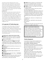
When using the welder in a gasless configuration the shielding gas is 

created from the flux within the welding wire.   

When using the welder outside, you may need to erect a wind break 

to make sure the shielding gas is not blown away, thereby leaving a 

poor quality weld. 


10.2 Gas/No-Gas Selection (for with DJMMIG195) 

The welder can be configured to weld, with or without a gas supply 

according to the type of welding wire being used.   

- Mild Steel solid core (With Gas),   

- Flux Cored (No Gas) 


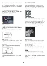
Welding without gas   

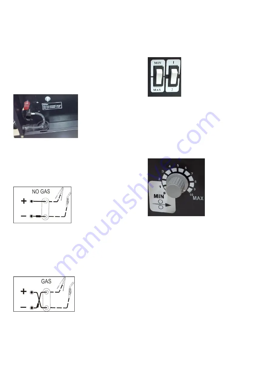
- If using 0.9mm flux cored wire, connect the terminal as shown.   

- The earth cable (Thicker Lead) should be connected to the positive 

(Red) terminal.   

- The cable from torch (Thinner Lead) should be connected to the 

Negative (Black) terminal   


Welding with gas   

- If using solid cored wire 0.6/0.8mm mild steel, connect the terminal 

as shown.   

- The earth cable (Thicker Lead) should be connected to the negative 

(Black) terminal.   

- The cable from torch (Thinner Lead) should be connected to   

the positive (Red) terminal.   


CONNECTING THE GAS SUPPLY   

- Connect a bottled gas supply to the small tube at the back of the 

welder. 


10.3 OPERATING THE WELDER 

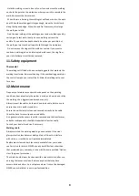
Setting the welding current   

-The welding current can be set to 2 different levels using the 

welding current adjustment switch . The required welding current 

depends on the material thickness, the required penetration depth 

and the welding wire diameter.   


Setting the wire feed speed   

-The wire feed speed is automatically adjusted to the current setting. 

The final wire feed speed setting can be made on the welding wire 

speed controller. It is advisable to start with the medium setting and 

to re-adjust the speed as necessary. The required quantity of wire 

depends on the material thickness, the penetration depth, the 

welding wire diameter and also the size of the gap to be bridged 

between the workpieces you wish to weld.   


Electrical connection   

- Before you connect the equipment to the mains supply make sure 

that the data on the rating plate are identical to the mains data.   

- The equipment may only be operated from properly earthed and 

fused shock-proof sockets.   

Connecting the earth terminal   

- Connect the welding set’s earth terminal in the immediate vicinity 

of the welding position if possible. Ensure that the contact point is 

bare metal.   

Welding   

- When all the electrical connections for the power supply and 

welding current circuit have been made, you can proceed as follows:   

- The workpieces for welding must be clear of paint, metallic 

coatings, dirt, rust, grease and moisture in the area where they are to 

be welded. 

- Set the welding current and wire feed 

Содержание DJMMIG130

Страница 1: ...0 ...

Страница 2: ...ostly repairs reduce downtimes and how to increase reliability and service life of the machine In addition to the safety regulations in the operating instructions you have to meet the applicable regulations that apply for the operation of the machine in your country Keep the operating instructions package with the machine at all times and store it in a plastic cover to protect it from dirt and moi...

Страница 3: ...e is deemed to be a case of misuse The user operator and not the manufacturer will be liable for any damage or injuries of any kind caused as a result of this Please note that our equipment has not been designed for use in commercial trade or industrial applications Our warranty will be voided if the equipment is used in commercial trade or industrial businesses or for equivalent purposes 5 Safety...

Страница 4: ...dip tanks storage areas ventilators If the work cannot be moved move combustibles at least 10M away out of reach of sparks and heat or protect against ignition with suitable and snug fitting fire resistant covers or shields Walls ceilings and floor near work should be protected by heat resistant covers or shields Fire watcher must be standing by with suitable fire extinguishing equipment during an...

Страница 5: ...tronic life supp t devices pacemakers Magnetic fields from high currents can affect pacemaker operation Persons wearing electronic life support equipment pacemaker should consult with their doctor before going near arc welding gouging or spot welding operations 5 3 6 To protect against shock Keep body and clothing dry Never work in damp area without adequate insulation against electrical shock Sta...

Страница 6: ...ble materials from the welding area ALWAYS Keep fire extinguisher handy Dry Powder C02 or BCF NOT Water NEVER remove any of the panels unless the machine is disconnected from the supply AND never use the machine with any of the panels removed NEVER attempt any electrical or mechanical repair unless your are a qualified technician If you have a problem with the machine contact your local dealer NEV...

Страница 7: ...Cored 0 6 0 9mm Wire Spool Capacity Up to 1Kg DJMMIG195 GAS NO GAS Mains Voltage 230V 50Hz Rated Max Supply Current 20A Output Amperage Range Duty Cycle 180A 10 No Load Voltage 23 43V Suitable Size Flux Cored 0 8 1 0mm Wire Spool Capacity Up to 1Kg 9 Assembly Installation 9 1 Fitting the welding screen Place the welding glass A over it in the frame for welding screen B Insert the handle welding ma...

Страница 8: ...der E upwards and Pull the pressure roller spring D and swing it downward Screw the appropriate contact tube for the welding wire diameter on to the torch and fit the gas nozzle turning it clockwise Set the adjusting screw for the roller brake I so that the wire can still be moved and the roller stops automatically after the wire guide has been braked 10 Operation Before any work on the machine it...

Страница 9: ...ferent levels using the welding current adjustment switch The required welding current depends on the material thickness the required penetration depth and the welding wire diameter Setting the wire feed speed The wire feed speed is automatically adjusted to the current setting The final wire feed speed setting can be made on the welding wire speed controller It is advisable to start with the medi...

Страница 10: ...or a time 12 Maintenance Frequency of maintenance operations depends on the operating conditions how intensively the welder is used and how clean or dirty the welding site is aggressive atmospheres etc Always inspect the cables both earth and torch cable before use to ensure they are in perfect condition Ensure the earth clamp is clean and secured correctly to the cable Check the hose for security...

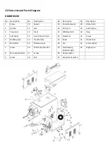
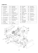
Страница 11: ...14 Transformer 6 Wire feed 15 Bottom panel 7 Screw 16 Thermal protection 8 Wire spool holder 17 Screw 9 Screw 18 Nut No Description No Description 19 Potentionmeter 28 Water joint 20 PC board 29 Earth clamp 21 Welding torch 30 Plug 22 Kickstand 31 Screw 23 Knob 32 Plastic foot 24 Fan 33 Screw spacer 25 Overheating indicator light 34 Right panel 26 Power switch 27 Adjustment switch ...

Страница 12: ... plain cushion 9 Heat element 21 M8 spring cushion 10 Wire feeding motor 22 Bottom panel 11 Rectifier 23 Handle 12 Vertical panel 24 M5x20 bolt No Description No Description 25 Switch 36 Ø3 steel wire 26 Main switch 37 Right panel 27 Indicator light 38 M5x70 bolt 28 Potentiometer handle 39 M5x25 bolt 29 Electrode holder 40 Back panel 30 Infix reed 41 Bottle bracket 31 Plug 42 M5x12 bolt 32 Earth c...

Страница 13: ...8 11 2020 MIG WELDER Part No DJMMIG130 DJMMIG195 EN IEC 60974 1 2018 A1 2019 EN 50445 2008 EN 60974 10 2014 A1 2015 EN 61000 3 11 2000 EN 61000 3 12 2011 2014 35 EU Low Voltage Directive 2014 30 EU EMC Directive ...

Страница 14: ...13 ...

Отзывы: