background image

Page 19

OPERATION INSTRUCTIONS

STARTING INSTRUCTIONS:

 Cold Engine

1. Push choke control lever fully forward.

2. Push throttle control lever to 1/2 setting.

3. Insert ignition key and turn to "Start" position.  When engine starts,

release ignition key.  Key will return to "Run" position.

4. Once engine starts to 

warm up, slowly move choke control lever to the

fully closed position.

5. Move throttle control lever to the 

wide open or maximum setting for actual

operation of the mower deck.

6. Engine must be operated at 

wide open or maximum setting to insure

adequate lubrication, cooling and cut quality of the mower deck.

Note:  6000 Series mowers will require a slightly longer warm-up period using

partial choke settings.

UNLOCK TRANSMISSION:

The freewheel levers are located on
each side of the mower below the seat
mount (flip up the foot deck to access
them).  Lift the levers slightly, push
them to the rear and down to release
the transmissions for free wheeling.  To
engage the transmissions lift the levers
slightly, pull them forward and then
down.

NOTE:  The tractor should never be
pulled at more than 2 miles per hour or
for any appreciable distance.

Содержание ZTR 6000 Series

Страница 1: ...6000 SERIES FORWARD MOUNT ZTR MOWERS Operator s Manual 2001...

Страница 2: ...use the mower read the operator s manual carefully and become completely familiar with the controls The information in this operator s manual applies to all Dixon ZTR 6000 Series Commercial Mowers Yo...

Страница 3: ...SPECIFICATIONS Page 11 SEAT ADJUSTMENT INSTRUCTIONS Page 12 CONTROLS Pages 13 16 OPERATIONINSTRUCTIONS Pages 17 21 CAREANDMAINTENANCE Pages 22 34 STANDARD SERVICE PARTS LIST Page 35 TROUBLESHOOTING Pa...

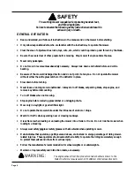
Страница 4: ...tand this manual to prevent injuries RIDING LAWNMOWERS IF IMPROPERLY OPERATED CAN CAUSE SERIOUS INJURY OR DEATH The most common causes of injury to the operator or bystander SAFETY BLADE CONTACT TIP O...

Страница 5: ...tes an imminently hazardous situation which if not avoided will result in death or serious injury Warning indicates a potentially hazardous situation which if not avoided could result in death or seri...

Страница 6: ...ogging chute Mow only in daylight or good artificial light Do not operate the mower while under the influence of alcohol or drugs Watch for traffic when operating near or crossing roadways Use extra c...

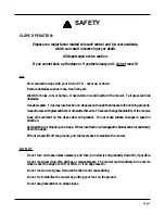
Страница 7: ...tchersorotherattachments Thesecanchangethestabilityofthemower Keep all movement on the slopes slow and gradual Do not make sudden changes in speed or direction Avoid starting or stopping on a slope If...

Страница 8: ...en out of the mowing area and under the watchful care of another responsible adult Be alert and turn mower off if a child enters the area Before and during backing look behind and DOWN for small child...

Страница 9: ...el tank or container opening at all times until fueling is complete Do not use a nozzle lock open device Never run a mower inside a closed area The exhaust fumes are toxic Keep nuts and bolts tight es...

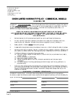
Страница 10: ...90 days from date of purchase 5 Warranty does not apply to damage in transit or incidents of misuse negligence accidents or alteration The use of parts or components other than those supplied by Dixo...

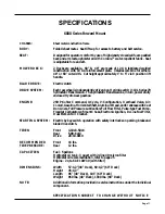
Страница 11: ...nd 4 Cycle V Configuration Overhead Valve Air Cooled Gasoline HorizontalShaft AluminumHead andCrankcasewithCast IronLiners FullPressureLubrication FullFlowFilter Pulse typeFuelPump FixedJetCarburetorw...

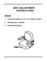
Страница 12: ...Page 12 SEAT ADJUSTMENT INSTRUCTIONS 6000 Series 1 Grasp seat slide adjuster and move it into adjustment position 2 Slide seat forward or backward 3 Release seat slide adjuster...

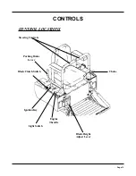
Страница 13: ...Page 13 CONTROLS CONTROL LOCATIONS Ignition Key Steering Controls Parking Brake Lever Blade Clutch Switch Light Switch Engine Throttle Choke Blade Height Adjust Lever...

Страница 14: ...at right hand side of mower To engage brake pull rearward To release brake move lever forward NOTE Always set parking brake before dismounting Release parking brake before moving mower HYDRO GEAR DRI...

Страница 15: ...rn on mower s own axis zero turning radius stop and move one lever to reverse position and the other to forward position BRAKING To brake mower move both levers in direction opposite of travel release...

Страница 16: ...t dealer for inspection and repair MOWER DECK CUT HEIGHT LIFT LEVER Located to the right and front of the operator Controls the cutting height Nine positions of adjustment Depress trigger and move lev...

Страница 17: ...udgement by the owner will prevent accidents TOWING Towing a trailer or other attachment that is too heavy could damage the drive or cause the mower to become unstable Limit loads to 500 pounds or les...

Страница 18: ...c Clutch or Manual Drive a With either electric blade drive switch turned on or manual lever turned forward parking brake in On position engine should not turn over or attempt to start when key switch...

Страница 19: ...r deck 6 Engine must be operated at wide open or maximum setting to insure adequate lubrication cooling and cut quality of the mower deck Note 6000 Series mowers will require a slightly longer warm up...

Страница 20: ...artial choke setting to start even if the engine has been operated for a period of time 4 Engine must be operated at wide open or maximum setting to insure adequate lubrication cooling and cut quality...

Страница 21: ...econd cutting 4 Keep The Underside Of The Mower Deck Clean Frequent removal of dried grass and dirt will allow the clippings to discharge correctly 5 Maintain sharp blade s throughout the cutting seas...

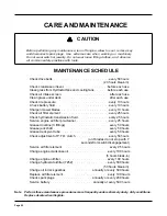
Страница 22: ...utch every 50 hours or if blades do not stop with 7 seconds from switch disengagement Service air filter element every 25 hours Change engine crankcase oil every 100 hours 5 hours break in Change engi...

Страница 23: ...frequent intervals Keep fluid level above the plates in each cell using distilled water OFF SEASON BATTERY STORAGE Identify each cable so cables can be reconnected to correct terminals Disconnect cab...

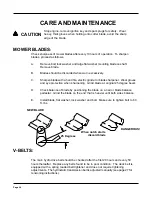
Страница 24: ...on when sharpening Grind blade at original 25 degree bevel D Check balance of blade by positioning the blade on a nail or blade balance pedestal Grind the blade on the end that is heavier until both s...

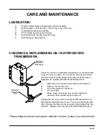
Страница 25: ...s of usage Do not remove the reservoir cap to check the oil level as this allows dirt to enter the transmission Replenish as needed with 20W 50 Mobil Super H D A Wipe area of oil reservoir cap clean o...

Страница 26: ...feeler gauge between the brake disc and the brake puck Tighten the castle nut with the feeler gauge inserted until the gauge fits snugly between the disc and puck The gap should not be so tight that...

Страница 27: ...mounting bracket B Tighten the tension adjust bolt until the belt is tight enough to prevent belt slippage Belt should deflect approximately 3 8 to 5 8 under moderate pressure Do not over tighten NOT...

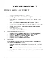
Страница 28: ...8 Shut off engine before removing the blocks B To Adjust IN Position of the Steering Controls 1 Remove the two front bolts lockwashers and washers which hold the fender cap 2 Pull the boot from the h...

Страница 29: ...the bolt at the lower end of the upper linkage assembly on the side that is slower Using a 1 8 allen wrench turn the setscrew 1 4 turn in It may take several test drives to get the mower to track str...

Страница 30: ...iddle hole on the anti buck cylinder holder will be in line with the slot on the foot deck locking device Use the quick release pin to secure the deck in the upright position LOWER AND REATTACH THE DE...

Страница 31: ...CKLOCKING DEVICE USE THIS HANDLE TO HELP DISENGAGEDOWNHANGER ANTI BUCKCYLINDER QUICKRELEASEPIN anti buck cylinder MIDDLEHOLE ONANTI BUCK CYLINDER HOLDER DECKLIFTBAR DECKLIFTHANDLECATCH QUICKRELEASEPIN...

Страница 32: ...shaft The fluid level should be level with the bottom of the threaded hole CHANGING THE FLUID IN DECK DRIVE GEARBOX 1 Rotate the deck into the upright position remove drain plug from bottom of gearbo...

Страница 33: ...er the deck should be leveled 4 Remove the clevis pin from the rear of the lift spring rod on the high side The lift spring rod is two parts one threaded into the other Turn the lift spring rod counte...

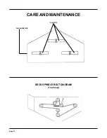
Страница 34: ...Page 34 DECK SPINDLE BELT DIAGRAM Top View CARE AND MAINTENANCE BLADETIP DISCHARGESIDE...

Страница 35: ...changes and air filter maintenance Protect your engine investment use only original equipment filters Model ZTR 6025 25HP Air Filter Pre Cleaner 78003 Engine Oil Filter 78006 IMPORTANT Some applicatio...

Страница 36: ...ver heated engine TROUBLESHOOTING disengage blades move steering control levers to neutral OUT position replace fuse charge or replace consult dealer consult dealer consult dealer refuel and or clean...

Страница 37: ...off seat safety switch 7 ENGINE OVERHEATED Air intake screen or fins clogged Fuel mixture too lean Oil level too low or too high Improper ignition timing Running engine too slow 8 ENGINE IDLES POORLY...

Страница 38: ...Page 38 NOTES...

Страница 39: ...DEL NUMBER MOWER SERIAL NUMBER PURCHASED FROM OWNER INFORMATION DATE OIL CHANGED DATE ENGINE TUNED Address Name DIXON INDUSTRIES INC A BLOUNT International Inc Co PO BOX 1569 COFFEYVILLE KS 67337 0945...

Страница 40: ...Exhaust from this product contains chemicals known to the State of California to cause cancer birth defects or other reproductive harm WARNING DIXON INDUSTRIES INC A BLOUNT International Inc Co PO BO...

Отзывы: