background image

NOTES


Page 37


Содержание ZTR 5501

Страница 1: ......

Страница 2: ...operator s manual carefully and become completely familiar with the controls The information in this operator s manual applies to all Dixon ZTR Model 5501 Mowers Your Dixon dealer will gladly provide a check out ride and answer any questions See your dealer for warranty service parts and repairs DIXON INDUSTRIES INC A BLOUNT COMPANY AIRPORT INDUSTRIAL PARK PO BOX 1569 COFFEYVILLE KS 67337 0945 316...

Страница 3: ...NTY POLICY Page 4 3 SPECIFICATIONS Page 5 4 SET UP AND SERVICE Pages 6 12 5 OPERATION INSTRUCTIONS Pages 13 14 6 CARE AND MAINTENANCE Pages 15 22 7 TROUBLESHOOTING Pages 23 25 8 PARTS ILLUSTRATIONS Pages 26 32 9 PARTS LIST Pages 33 36 ...

Страница 4: ...w slopes when the grass is dry and watch for bumps holes and other obstacles Test the slope with the blades off A good rule of thumb is Don t mow on a slope you can t back up Stay clear of drop offs especially if they are on the down side of a slope 4 THROWN OBJECTS The fast spinning mower deck blade can strike stones or other objects which can be hurled into the path of a bystander To prevent thi...

Страница 5: ...ttended Your Dixon mower is equipped with a weight sensitive switch that kills the engine when operator leaves the seat while blades are engaged Note This important safety feature must be tested prior to each mowing This may be done by starting engine engaging blades and then rising slightly from seat If engine does not stop see your dealer for necessary repair 10 Before adjusting or servicing you...

Страница 6: ...nd screws tight to be sure the mower is in safe working condition 20 To reduce fire hazard keep the engine free of grass leaves or excessive grease 21 The mower should be stopped and inspected for damage after striking a foreign object or if it starts vibrating and any damage should be repaired before restarting and operating the mower 22 When mowing proceed as follows A Mow only in daylight or in...

Страница 7: ...s Covers etc Limited to 90 days from date of purchase 5 Warranty does not apply to damage in transit or incidents of misuse negligence accidents or alteration The use of parts or components other than those supplied by Dixon Industries Inc VOIDS ALL WARRANTY 6 The following items are not covered by this warranty policy a Pick up and delivery charges for transportation of mower to and from an Autho...

Страница 8: ...U 1 OL Series 70 hydrostatic transmissions are serviced with any high quality 10W 30 motor oil The oil is filtered by a 10 micron oil filter Recommended service interval for filter is after the first 250 hours of operation then after every 400 hours of operation If the system becomes contaminated by dirt or other foreign debris both oil and filter must be replaced immediately ENGINE 20 HP Kohler M...

Страница 9: ...Page 6 SET UP AND SERVICE 1 Seat Assembly Instructions 2 Upper Control Lever Installation 3 Mower Deck Installation 4 Deck Leveling 5 Final Preparation ...

Страница 10: ...O NOT TIGHTEN SECURELY 4 Insert 1 1 4 20 X 3 4 Phillips machine screw through remaining hole in bracket and start screw threads DO NOT TIGHTEN SECURELY 5 Repeat steps 2 through 4 for the other armrest 6 Tighten all screws 7 Align back cover to seat back Secure with 4 14 X 5 8 wood screws and 4 5 16 SAE washers in recesses provided 8 Slide armrest onto mounting bracket pin 9 Insert set screw in rea...

Страница 11: ...tach seat straps using 4 5 1 6 18X1 tapping screws 14 Place seat assembly on body and connect safety switch 15 Place 1 seat spacer 1849 on each stud protruding through seat bottom and insert studs through slots in body Firmly hold seat assembly against body with one hand while body is raised to fully open position Continue to hold seat against body to prevent damage to seat safety switch wiring 16...

Страница 12: ...hen second flat washer 3 Push control lever into the neutral slot and install 2 cup washers 1 flat washer and jam nut See illustration 4 Tighten jam nut Proper tightness or tension on jam nut is achieved when swing out movement of upper control levers requires some pressure Levers should not fall to the side or be sloppy in movement 5 Repeat above procedure on left side Page 9 ...

Страница 13: ...nger rods on lift frame Slide lift plate on hanger rods small holes in lift plate will face rear of mower and start nylok nuts on each hanger rod until approximately 1 2 inch of threads are exposed 3 Position mower deck under chassis 4 Raise front of mower deck and slide front support rod through lift frame and tabs on mower deck Install hair pin clips on front and rear of support rods 5 Move lift...

Страница 14: ...Move to the opposite side check that measurement is the same If adjustment is required turn the nut on the bottom of the front threaded adjuster up or down until both side to side measurements are equal Retain measurement D Rotate or turn both outer blades to align with the deck in front to rear manner Move to the left rear threaded adjuster left rear is designated from operator position on the mo...

Страница 15: ...sis 6 Observe proper battery polarity when re connecting leads on chassis Always connect positive lead first ENGINE SERVICE Final preparation of engine should be completed using engine service manual provided with mower INITIAL START AND HYDROSTAT TRANSMISSION CHECK 1 Final hydrostat checks have been performed at the factory however it is necessary to check that the pressure relief bypass on each ...

Страница 16: ...VE SYSTEM Allows the mower to turn on its own axis zero radius Each lever controls one side of the mower The pressure required to operate the mower is very light and a minimum of 1 2 hour should be spent simply driving the mower in a non mowing application to gain the confidence necessary to mow like a pro LEVER MOVEMENTS No shifting or clutching required TO GO FORWARD Release parking brake From n...

Страница 17: ...ould be set to the maximum or wide open setting to insure adequate cooling of the engine and to maintain mower deck blade speed while mowing MOWER DECK CUT HEIGHT LIFT LEVER Controls the cutting height of the mower deck Seven positions of adjustment in which the very top or highest notch is used for transporting the mower in a non mowing situation Located in front of operator on the right side of ...

Страница 18: ...nit if failure should occur MAINTENANCE SCHEDULE To insure a long and trouble free service life on all the components used on the Model 5501 a regular and thorough maintenance schedule should be followed As with any type of precision made equipment a certain amount of initial bedding in or seating of the components will take place The following items should be checked after the first 10 hours of o...

Страница 19: ...inserted after removal 9 Reinstall the clutch to the engine Be sure to torque the mounting bolt back to 50 ft Ibs B OHMS TEST 1 Disconnect clutch from mower wiring harness which is located on the right side of the mower frame 2 Set the multi meter on RX1 and attach the two leads to the two wires coming from the electric clutch 3 The reading you receive should be between 2 4 to 2 9 OHMS 4 If the re...

Страница 20: ...eck from under chassis 3 Reverse procedure to re install deck assembly CUTTER BLADE REMOVAL 1 Carefully place deck assembly in a manner which will allow access to the blade bolts Hold blade from turning while bolt is removed from the center of each hub assembly Caution wear heavy thick gloves when holding onto cutter blade avoid the sharp e d g e o f t h e b l a d e 2 When reassembling blades to h...

Страница 21: ...parking brake Caution should be used when releasing parking brake as mower may tend to creep or move prior to adjustment If adjustment is required loosen lock nuts at each end of the control rods and back off the tension on each spring block Turn control rods in or out until neutral is obtained on each hydrostat Re tighten lock nuts and tension bolts on spring blocks 4 Forward travel speed adjustm...

Страница 22: ...ADJUSTMENT POINTS FOR T BOX BELT TENSION Page 19 ...

Страница 23: ...FORWARD LEVER STOP ADJUSTMENT Page 20 ...

Страница 24: ...s is not recommended as damage to seals and bearings could occur Using a hand pressure grease gun lubricate each front wheel to allow even distribution of grease within the wheel rotate or spin each front wheel after 3 pumps of the grease gun Repeat process until the appearance of grease is noted completely around each caster axle ENGINE OIL CHANGES OIL RECOMMENDATIONS SERVICE INTERVALS Refer to s...

Страница 25: ...stiff brush can be used to loosen excess grass and dirt build up Avoid directing water pressure onto the mower deck hub assemblies electrical wiring and engine components such as air filter openings To remove excess water which accumulated during washing of the mower either blow off with compressed air if available or start the engine allowing a long enough operation time to dry thoroughly It is a...

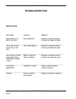
Страница 26: ...ler is also available to provide assistance to you SITUATION CAUSES REMEDY Poor cut quality Ground speed Reduce mowing speed Poor cut quality Loose belts Adjust per operators manual Poor cut quality Engine RPM too low Increase engine RPM to maximum Poor cut quality Dull or bent blades Sharpen or replace as required Poor cut quality Unlevel mower deck Adjust per operators manual Poor cut quality Gr...

Страница 27: ... T Box belts slipping Adjust per operators manual Consult your dealer for repair Loss of power on both wheels after being operated for a length of time Belt from engine to T Box is slipping Adjust per operators manual Consult your dealer for repair Poor driving performance Operation of mower Review operators section of owners manual Oil leaks Loose or missing hose clamps Tighten or replace as requ...

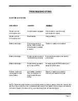
Страница 28: ...g correctly Have electrical system checked by your dealer Battery discharge Engine being operated at too low an RPM Increase engine RPM Contact your dealer for information Electric clutch will not engage mower deck blades Low battery condition Poor connections on clutch switch Broken wiring Repair or replace as required Consult your dealer for repair NOTE Electrical system failures are generally s...

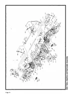
Страница 29: ...Page 26 ...

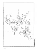
Страница 30: ...Page 27 ...

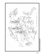
Страница 31: ...Page 28 ...

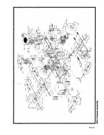
Страница 32: ...Page 29 ...

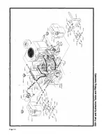
Страница 33: ...Page 30 ...

Страница 34: ...Page 31 ...

Страница 35: ...Page 32 ...

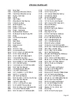
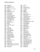
Страница 36: ... HH BoltGR5 3002 5 16 18X21 2 HHBoltGR8 3231 9 1 6 Std Flat Washer 3005 5 16 18UNCHexNut 3235 1 0 24 X 5 8 Phillips Pan HD Screw 3006 5 16 18X14 HHBoltGR5 3237 Eye Bolt 5 1 6 X 6 00 3007 1 4 20 UNC Hex Nut 3243 5 16 18X31 4 HHBoltGR5 3008 1 4 ID X 3 4 OD Flat Washer 3247 6 20 X 1 2 Phillips Pan Hd Screw 3009 5 16 18 UNC X 1 3 4 HH Bolt GR8 3248 5 1 6 ID X 1 8 Thick Washer 3012 3 8 16UNCHexNut 3249...

Страница 37: ...HH Bolt GR5 Alt Head 3852 Spring 3360 5 16 18 X 4 HH Bolt GR5 Alt Head 3857 Fuel Line 23 3361 Stud 1 2 13X2 3861 Control Panel 50 3362 5 16 18X1 Tap Screw 3874 Seat Knob 5 1 6 18 3364 Washer Bent 3876 Caster Spring 3368 1 4 20 X 3 4 HWH Tap Screw 3878 Caster Plug 3369 1 4 20 U Nut 3882 Hand Grip Notched 3370 1 4 Square Key X 2 50 3887 Chrome Lug Nut 3373 6 32X1 2 HWH Slotted 3889 Drive Pulley 1 13...

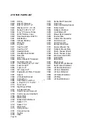
Страница 38: ...11 Deck Drive Belt 5257 Brake Drum Keyed 6168 Trash Guard 5283 Link 6260 Blade Washer 5500 T Box 6395 Blow By Baffle 50 5501 Mount Plate 6402 Deflector Pin 5502 Mount Shim 6406 Deflector Spring 5503 T Box Guide Left 6744 Spring 5504 T Box Guide Right 7034 Belt Keeper 5515 Idler Cable 8177 Caster Tire 50 5522 Brake Link Right 8178 Caster Rim 50 5525 Brake Link Left 8179 Caster Bearing 50 5530 Contr...

Страница 39: ... Shaft Tapped Long 8576 Rear Rim 9362 Idler Assembly 9276 8577 Rear Tire 9366 Deck Baffle 8689 Mower Blade 50 Standard 9372 Body Brace 8788 Tie Bar Anchor Kit 9377 Brake Lever 8791 Convuluted Loom 1 2 X 60 9405 Deflector Mount Bracket 8853 Fuel Line 22 5 9411 Seat Frame Weldment 8854 Fuel Line 6 9618 Lift Handle Weldment 8855 3 8 Hose 26 5 9623 Lift Cam Drilled RH 9023 Engine Mount Plate Forward 9...

Страница 40: ...NOTES Page 37 ...

Страница 41: ...NOTES Page 38 ...

Страница 42: ...DIXON INDUSTRIES INC A BLOUNT COMPANY AIRPORT INDUSTRIAL PARK PO BOX 1569 COFFEYYILLE KS 67337 O945 316 251 2QOO FAX 316 251 4117 ...

Отзывы: