background image


CARE AND MAINTENANCE


PROCEDURE FOR ELECTRIC CLUTCH  ADJUSTMENT


Electric clutches require periodic Air Gap adjustments to extend the life of the clutch.  Listed below is 

both an Air Gap adjustment procedure and an Ohms test to check for a faulty coil within the clutch. 

No replacement parts are available to repair a faulty assembly. The entire clutch must be replaced.


A. AIR GAP ADJUSTMENT


1.   Remove the clutch from the engine. This is recommended because it is easier to verify the


gap- 

2.  Locate the three rivet joints which fasten the leaf springs to 

the armature, (figure 1) 

3.  Rotate the pulley until these rivet joints are located midway 

along the edge of the triangular field adapter, (figure 1) 

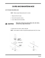
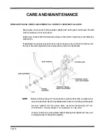
4.  Locate the three holes in the brake plate, one near each 

adjustment nut. (figure 2) 

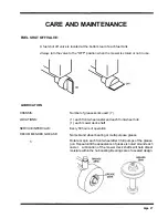
5.  Insert a .012 inch feeler gauge into one of the three 

windows. Be careful to position the feeler gauge 

between the rotor and armature faces, (figure 3) 

6.   Tighten the adjusting nut adjacent to the window with the 

feeler gauge inserted until the gauge fits snugly between 

the rotor and armature. The gap should not be so tight that the feeler gauge cannot be 

reinserted after removal.


7.  Repeat Steps 5 and 6 at the other two windows. 

8.  Re-check the air gap at each window and make minor 

adjustments as necessary to achieve a consistent 

.012 inch air gap. 

9.  Reinstall the clutch to the engine. Be sure to torque the 

mounting bolt back to 50 ft. Ibs. 

B. OHMS TEST:


1.  Disconnect clutch from mower wiring harness which is 

located on the right side of the mower frame. 

2.  Set the multi-meter on RX1 and attach the two leads to the 

two wires coming from the electric clutch. 

3.  The reading you receive should be between 2.4 to 2.9 OHMS. 

4.  If the resistance is outside this range the clutch coil is faulty. 

5.  If the clutch coil is faulty, the clutch must be replaced. 


Page 37


Содержание ZTR 5020

Страница 1: ......

Страница 2: ...mower read the operator s manual carefully and become completely familiar with the controls The information in this operator s manual applies to all Dixon ZTR Series Mowers Your Dixon dealer will glad...

Страница 3: ...SAFETY Pages 1 6 WARRANTY POLICY Page 7 SPECIFICATIONS Page 8 9 SEAT ADJUSTMENT Page 10 CONTROLS Pages 11 14 OPERATION INSTRUCTIONS Pages 15 22 CARE AND MAINTENANCE Pages 23 37 STANDARD SERVICE PARTS...

Страница 4: ...RIDING LAWNMOWERS IF IMPROPERLY OPERATED CAN CAUSE SERIOUS INJURY OR DEATH The most common causes of injury to the operator or bystander Page 2 read and understand this manual to prevent injuries...

Страница 5: ...an imminently hazardous situation which if not avoided will result in death or serious injury Warning indicates a potentially hazardous situation which if not avoided could result in death or serious...

Страница 6: ...and while backing Be aware of the mower discharge direction and do not point it at anyone Do not operate the mower without either the entire grass catcher or the deflector in place Slow down before t...

Страница 7: ...r attachments These can change the stability of the mower Keep all movement on the slopes slow and gradual Do not make sudden changes in speed or direction Avoid starting or stopping on a slope If tir...

Страница 8: ...n out of the mowing area and under the watchful care of another responsible adult Be alert and turn mower off if a child enters the area Before and during backing look behind and DOWN for small childr...

Страница 9: ...ower free of grass leaves or other debris buildup Clean up oil or fuel spillage Allow mower to cool before storing Stop and inspect the equipment if you strike an object Repair if necessary before res...

Страница 10: ...from date of purchase 5 Warranty does not apply to damage in transit or incidents of misuse negligence accidents or alteration The use of parts or components other than those supplied by Dixon Indust...

Страница 11: ...n by a HydroGear BDU 10L Series 70 hydrostatic transmission The hydrostatic transmissions in turn power a fully enclosed HydroGear gearbox ENGINE 17HP Briggs Stratton Intek overhead valves replaceable...

Страница 12: ...endently driven by a HydroGear BDU 10L Series 70 hydrostatic transmission The hydrostatic transmissions in turn power a fully enclosed HydroGear gearbox ENGINE 20HP Briggs Stratton Intek overhead valv...

Страница 13: ...assembly and upper body rearward 3 Loosen two front seat adjustment knobs P N 3978 and slide seat forward or backward to desired position 4 Re tighten front seat adjustment knobs P N 3978 DO NOT oper...

Страница 14: ...Page 12...

Страница 15: ...rated parking brake is located at left hand side of mower To engage brake pull lever up and to the rear To release brake move lever forward and down NOTE Always set parking brake before dismounting Re...

Страница 16: ...urn on mower s own axis zero turning radius stop and move one lever to reverse position and the other to forward position BRAKING To brake mower move both levers in direction opposite of travel releas...

Страница 17: ...of the electrical system is by 1 15 amp circuit breaker If circuit breaker trips push button to reset If this condition repeats consult dealer for inspection and repair MOWER DECK CUT HEIGHT LIFT LEVE...

Страница 18: ...nt accidents DRINK CUP HOLDER located on left rear fender is for transport or carrying ONLY Mower usage requires that both hands be free to control individual levers DO NOT ATTEMPT operation of mower...

Страница 19: ...engine should not turn over or attempt to start when key switch is moved to the start position b In a SAFE AREA away from bystanders start the engine place throttle setting at maximum or full Engage t...

Страница 20: ...ine starts release ignition key Key will return to Run position 4 Once engine starts to warm up slowly move choke control lever to the fully closed position 5 Move throttle control lever to the wide o...

Страница 21: ...etting for actual operation of the mower deck 4 Engine must be operated at wide open or maximum setting to insure adequate lubrication cooling and cut quality of the mower deck DO NOT operate the engi...

Страница 22: ...ly on first cuttings or if the lawn is heavily fertilized 4 Do Not Attempt To Cut Grass When It Is Wet Mulching performance will be very poor under wet grass conditions 5 Maintain A Sharp Blade Throug...

Страница 23: ...ngs 5 Use only the correct blade s Some grass catching attachments require a high lift blade See your dealer for advice on the type of blade s needed for your mower 6 Maintain Sharp Blade s Throughout...

Страница 24: ...h with each pass Some applications may require a second cutting 4 Keep The Underside Of The Mower Deck Clean Frequent removal of dried grass and dirt will allow the clippings to discharge correctly 5...

Страница 25: ...bove the turf This setting should prove ideal under most mowing conditions Adjustment Some mowing applications may require lowering of each front roller To lower the roller remove the pin spring washe...

Страница 26: ...attention 1 Drive system belts and controls 2 Mower deck belts 3 Tire pressures 4 HydroGear oil tank 5 Tightness of all nuts and bolts 6 Battery fluid level 7 Engine oil Before each use or every 8 hou...

Страница 27: ...front of mower 2 Hold or block blade from turning 3 Loosen blade nut and remove blade Wear heavy thick gloves when holding onto cutter blade avoid the sharp edge of the blade 4 Tighten blade nut secu...

Страница 28: ...by springs which push the deck assembly forward and do not require any additional adjustment to be made MOWER DECK SERPENTINE BELT Model ZTR 5424 Model ZTR 5020 42 50 60 P N P N P N P N 6109 6109 1300...

Страница 29: ...1 each front wheel caster and each front wheel hub 1 each mower deck shaft SERVICE INTERVALS Every 50 hours of operation RECOMMENDED GREASE Name brand wheel bearing or multi purpose grease fi Rotate o...

Страница 30: ...lt in severe injury or death All slopes require extra caution If you cannot back up the slope or if you feel uneasy on it do not mow it WHEEL REVERSAL Installation instructions marked with an asterisk...

Страница 31: ...ining oil OIL FILL 1 Push the valve body in and twist into the detent notch 2 Clean any spilled oil from engine and chassis 3 Refill engine with type and quantity of oil recommended by the engine manu...

Страница 32: ...of engine to mower deck drive belt has been placed in position during assembly of the lift frame at the factory For shipment purposes the brake link has been secured with a cotter pin and washer REMOV...

Страница 33: ...ly 1 2 inch of threads are exposed 3 Position mower deck under chassis 4 Raise front of mower deck and slide front support rod through lift frame and tabs on mower deck Install hair pin clips on front...

Страница 34: ...t measurement is the same If adjustment is required turn the nut on the bottom of the front threaded adjuster up or down until both side to side measurements are equal Retain measurement D Rotate or t...

Страница 35: ...of an inch free play or movement at a mid point between the pulleys on the hydrostats and T box Each hydrostat has a bypass relief pin located at the rear of the hydrostatic unit A bypass keeper is pr...

Страница 36: ...the belt At this time check that the cable which pulls the idler to a neutral position has approximately 1 1 2 to 2 inches of free play If adjustment is required loosen the lock nuts on the cable blo...

Страница 37: ...brake Caution should be used when releasing parking brake as mower may tend to creep or move prior to adjustment If adjustment is required loosen lock nuts at each end of the control rods and back of...

Страница 38: ...required loosen the lock nuts on the lever stop and turn the bolt in until the lever hits the stop block before resistance is felt in the hydrostat NOTE Balance of travel speed If mower tends to pull...

Страница 39: ...ne of the three windows Be careful to position the feeler gauge between the rotor and armature faces figure 3 6 Tighten the adjusting nut adjacent to the window with the feeler gauge inserted until th...

Страница 40: ...peration temperatures 20 W 50 Cold climate usage 10 W 40 Another alternative that will provide excellent all climate performance and extended time between oil changes is a 15 W 50 synthetic engine oil...

Страница 41: ...connections clean and tight CLEANING THE MOWER Wash mower periodically Clean above and below deck NOTE Allow mower to cool before washing If bearings are hot they will draw moisture inside as they dry...

Страница 42: ...TE MODEL 50 DECK BLADES Standard Hi Lift P N 9443 P N 9444 BELTS Engine To Mower Deck Serpentine Belt Engine To T Box T Box To Hydros Grass Blower Belt P N 6111 P N 1300 P N 1714 P N 1765 P N 4983 EST...

Страница 43: ...of service required for engine oil changes and air filter maintenance Protect your engine investment use only original equipment filters Model ZTR 5424 17HP Pre Cleaner Foam Element Cartridge Air Clea...

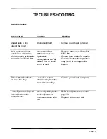
Страница 44: ...vailable to provide assistance to you SITUATION CAUSES REMEDY Poor cut quality Poor cut quality Ground speed Incorrect engine to mower deck belt Reduce mowing speed Refer to page 39 for part numbers P...

Страница 45: ...ir locked low or no oil return to tank Replace with correct Dixon P N 5565 filter Consult your dealer for repairs Continued attempted operation may result in damage to the system Drive system function...

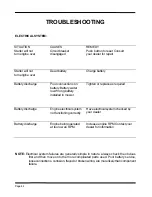
Страница 46: ...er Tighten or replace as required Battery discharge Engine electrical system not functioning correctly Have electrical system checked by your dealer Battery discharge Engine being operated at too low...

Страница 47: ...STRIES INC A BLOUNT International Inc Co PO BOX 1569 COFFEYVILLE KS 67337 0945 316251 2000 FAX 316 251 4117 DATE PURCHASED MOWER MODEL NUMBER MOWER SERIAL NUMBER DM PURCHASED FROM Name Address DATE OI...

Страница 48: ......

Отзывы: