

dIXEL
Operating and Instructions Manual
1592006100
1592006100 XB570L GB r1.0 04.11.2004.doc
XB570L
3/6
rS2 (
-50
÷
50°C; 1°C/1°F)
Room probe Set point
for the second phase: it
prevents temperature from reaching a too low value during the second
phase.
Pd2
OFF
÷
4.0h;
res.
10 min
Maximum time for second phase.
iS3 (
-50
÷
50°C; 1°C/1°F)
Insert Probe Set point
to stop the third (and last)
phase: when the temperature measured by the third probe reaches this
value the whole cycle is ended.
rS3 (
-50
÷
50°C; 1°C/1°F)
Room probe Set point
for the third (and last) phase:
it prevents temperature from reaching a too low value during the third
(and last) phase.
Pd3 (
OFF
÷
4.0h; 10 min)
Maximum time for the third phase.
dbH (yes / no) defrost before the hold phase
HdS (-50÷50 - OFF; 1 °C / 1°F) Set point of the holding phase
. With “OFF”
the hold phase is disabled.
IMPORTANT NOTE:
If the duration time of a phase is set at the OFF value,
the corresponding phase is disabled. E.g. If
Pd3
= 0FF the third phase of the
cycle is not active.
14.2 . HOW TO USE THE INSERT PROBE.
By means the insert probe, the internal temperature of products can be
checked. This measure is used to end the various phase of the cycle. A
special internal function detect if the inset probe is not used, in this case the
cycle is made by time
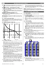
14.3 EXAMPLE OF A BLAST CHILLER CYCLE.
The following drawing explains how a Blast Chiller cycle can be done.
14.3.1 First phase: “Hard chill”.
It is normally used to fast chill hot foods. E.g. from 80°C / 170°F to 20°C /
70°F
During “
Hard Chill
”, both compressor and fan are always on until the
rS1
temperature is reached. At this point compressor is turned on end
off so as to keep the temperature of the room at the
rS1
value. “Hard
Chill” ends when the temperature measured by the third probe reaches
the
iS1
value. Normally
rS1
is set at few degrees below zero.
14.3.2 Second
phase: “Soft chill”.
The
Soft Chill
starts when the Hard Chill ends. It is used to prevent thin
layer of ice from forming on the product. The Soft Chill lasts until the
temperature measured by the third probe reaches the set point
iS2
(usually 4 or 5°C).
During Soft Chill the temperature of the room is regulated by the ambient
probe with the set point
rS2
(normally at 0 or 1 °C / 32 or 34°F). When
the box temperature reaches the
rS2
value compressor is turned on end
off so as to keep the temperature of the box at this value.
14.3.3 Third phase: “Freezing cycle”.
Freezing Cycle: used to fast freeze foods.
The Freezing Cycle starts when the Soft Chill ends. During the “Freezing
Cycle” both compressor and fan are always on until the
rS3
temperature
is reached. At this point compressor and fans are turned on end off so as
to keep the temperature of the room at the
rS3
value (normally some
degrees below
iS3)
. Freezing Cycle ends when the temperature
measured by the third probe reaches the
iS3
value (normally -18°C /
0°F), in any case it ends when the maximum time
Pd1 + Pd2 + Pd3
has
expired.
14.3.4 End of the Blast Chill cycle and starting of the Hold Mode.
When the Blast Chiller cycle ends an alarm signal is generated: buzzer
and alarm relay is turned ON, the display shows the message “End”
alternating with the room temperature.
The alarm automatically stops after 30min or by pressing any key.
At the end of the Blast Chiller cycle the controller can start the “Hold
mode” keeping the room temperature at the value set in HdS parameter.
If HdS = OFF, the machine is turned OFF.
NOTE1:
with
dbH = yES
a defrost is done before the holding phase.
NOTE2:
If the end cycle temperature IS3 is not reached by the maximum
time Pd1+Pd2+Pd3 the instrument keep on working, but the alarm message
“OCF”
is given.
15. Function And Parameter Programming Menu
15.1 FUNCTION
MENU
Includes all the main functions controlled by the instrument.
15.2 ACCESS
PROCEDURE:
1. Hold
the
SET
and
DOWN
keys pressed for few seconds, until the label of
the first function will be displayed.
2. The
UP
and
DOWN
keys are used to cycle backwards or forward in the
menu.
3. By pressing the
SET
key the currently displayed function is enabled.
4. To go back to the previously Menu press the
SET
and
DOWN
keys
together
15.3 LIST OF FUNCTIONS
15.3.1 “Prb”: probe display
It permits the user to display the temperatures measured by the probes.
•
rPr:
displays for 10s the temperature measured by the room probe.
•
EPr:
displays for 10s the temperature measured by the evaporator
probe.
•
iPr:
displays for 10s the temperature measured by the insert probe.
NOTE1
If a key is pressed when a temperature is displayed, the
instrument go back to show the label of the probe (rPr, EPr, iPr).
NOTE2:
If the selected probe is broken, the follow alarm labels will be
displayed:
rPF
for the room probe,
EPF
for the evaporator probe,
iPF
for
the insert probe.
15.3.2 “Pr1”: user parameters
“Pr1”
includes all user accessible parameters. If no parameter would be
present in the menu, the label “Pr2” will be displayed.
15.3.3 “Pr2”: installer parameters
“
Pr2
”: includes all the instrument’s parameters (at installer level). It can be
accessed through a security code. Hence it is possible to modify all
parameters and add or remove parameters from “Pr1” (user level) by
pressing
“SET”
+
“UP”
. When a parameter is enabled at user level,
LED
(Alarm LED) is on.
15.3.4 “FCy”: cycle management
The FCy menu contains the Cy1, Cy2, Cy3, Cy4 submenu. Each
submenu contains all the configurable parameter of the cycle as shown
in the following drawing:
Cy1
Fcy
Cy2
Cy3
Cy4
rS1
Pd1
dbH
iS2
rS2
Pd2
iS3
rS3
Pd3
iS1
dbC
HdS
rS1
Pd1
dbH
iS2
rS2
Pd2
iS3
rS3
Pd3
iS1
dbC
HdS
rS1
Pd1
dbH
iS2
rS2
Pd2
iS3
rS3
Pd3
iS1
dbC
HdS
rS1
Pd1
dbH
iS2
rS2
Pd2
iS3
rS3
Pd3
iS1
dbC
HdS
15.3.5 “Sto”: cycle length
The
Sto
menu records the real length of a cycle and the real length of
each single phase. It contains the following sub-menu:
tCy
: cycle duration,
tP1
: first phase duration;
tP2
: second phase
duration;
tP3
: third phase duration.


