background image

CONTROL PCB 

WARNING: If you don’t screw them now, you won’t be able to do it later!!!  Make sure they are 

tightly fastened, use a tool for this purpose.

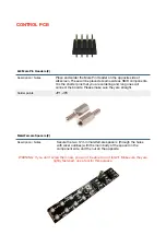
2x4 Male Pin Headers (2)

Description / Notes

Place and solder the Male Pin Header on the opposite side of 

silkscreen. These will be placed at same side as SMD components. 

It is the shorter pins that you are soldering and long ones will 

connect the boards. Please make sure they are straight.

Solder points

JP1, JP3

Male/Female Spacers (2)

Description / Notes

Secure the two 12 mm male/female spacers  (through the holes 

with silver outlines) with the main body of the spacer on the 

component side, and the nut on the opposite.

Содержание Mutes

Страница 1: ...be careful and doublecheck all your steps In this semi kit you get two boards with SMD pre assembled front panel and the rest of the mechanical components needed to finish a Mutes modules Once again thanks a lot for choosing Mutes GOOD LUCK _______________________________________________________________________________________ MAIN PCB We will start assembling the Main PCB smallest one This board ...

Страница 2: ...e Please make sure they are straight Solder points JP2 JP4 Power Connector 1 Description Notes Place the power connector at POWER at silkscreen side same side as Vactrols ensuring it is facing out from the edge of the PCB Solder points 2x5 10 pin at the bottom of the board see image below ...

Страница 3: ...the opposite side of silkscreen These will be placed at same side as SMD components It is the shorter pins that you are soldering and long ones will connect the boards Please make sure they are straight Solder points JP1 JP3 Male Female Spacers 2 Description Notes Secure the two 12 mm male female spacers through the holes with silver outlines with the main body of the spacer on the component side ...

Страница 4: ... Place the mini jacks on the PCB ensuring they are on the side with the silkscreen but don t solder them until the front panel is in place with all nuts screwed to it This way it s easier to solder them in the right position Keep in mind that the front panel holes are quite narrow and it is almost impossible to place it with all the components already soldered SWITCHES Remove washers and nuts from...

Страница 5: ...rs are close to the LED solder points Be careful not to bridge them as this may cause a short Doublecheck your soldering Just in case _______________________________________________________________________________________ WARRANTY DISCLAIMER These pre assembled boards are part of batch used for assembled modules that were tested right All the PCBs were checked with flying probe test After assembly...

Страница 6: ......

Отзывы: