background image


14


DiViS 

www.

DiViS

DVR.com


1)  Connect 1~16 channel video pigtail cable to the top connector.   

2)  Connect 1~16 channel audio pigtail cable to the bottom connector.   

3)  Connect CCTV monitor.   

4)  Connect I/O cable to the sensor port.   

5)  Connect the other side of the I/O cable to the I/O connector.   
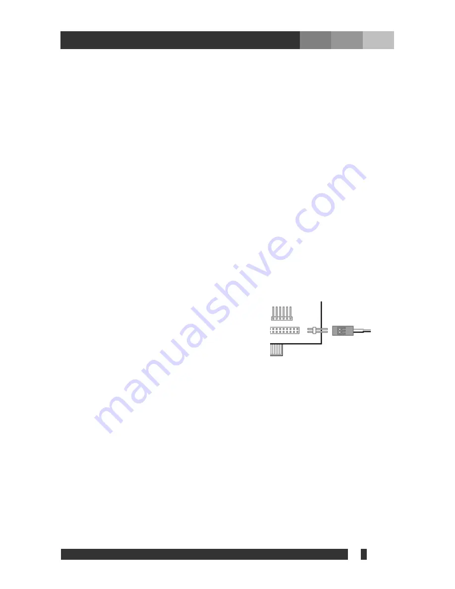
6) Connect 

watchdog 

cable. 

  (White cable must go left and Black cable must go side   

of the connector) 

7)  Extension Relay connector : Connect extension relay 

8)  Connect Power cable 

9)  Connect 17~32 channel video pigtail cable to the top connector.   

10) Connect 17~32 channel audio pigtail cable to the bottom connector.   

11) Connect CCTV monitor.   

12) Connect video cable to the video port.   

13) Connect the other side of the video cable to the video connector.   


Содержание D1 Series

Страница 1: ...System Digital Video Recorder www DiViSdvr com DiViS DVR com All contents of this document may change without prior notice and actual product appearance may differ from depicted herein DiViS DVR Hardware Installation Guide D1 Series ...

Страница 2: ...or 96032HSD1 5 3 Products and Components 6 3 1 DVR Board 6 3 2 Optional Accessories 6 4 Board Description 7 4 1 48016HSD1 7 4 2 96032HSD1 8 4 3 I O Board 10 5 Installation 11 5 1 48016HSD1 Installation 11 5 1 1 Pigtail Type 11 5 1 2 Back panel Type 12 5 2 96032HSD1 Installation 13 6 Accessories 15 6 1 RS422 485 Converter 15 Index ...

Страница 3: ...are explanation please refer to Installation and User s Guide This guide book is applicable to among DiViS products 48016HSD1 96032HSD1 board The pictures and the name of the products are subject to change however the usage may be similar Please contact us through the LiveChat service for any technical questions Website https divisdvr com Introduction ...

Страница 4: ... different camera shots to be displayed onscreen at the same time Other display features include enlarging all displayed cameras or just one ㆍ PAN TILT ZOOM FOCUS Capabilities Each connected camera can be manipulated through the DiViS main program as long as each camera supports such capabilities ㆍ Auto Rebooting System When DiViS detects an error or malfunction within the system it will automatic...

Страница 5: ...otocol Support DiViS supports network access which allows administrators to login to DiViS main and remotely access all the features provided locally ㆍ POS Access Control ATM Support Record data from external devices POS Access Control ATM etc with DVR video images Text Search allows to search data from external devices with DVR video image when event occurs This will raise the level of integrity ...

Страница 6: ...saver and Standby mode I Turn off System Standby mode II Turn off Screen saver III Turn off all the energy saving feature 2 2 Recommendation for 96032HSD1 Recommend to use Intel Chipset mother board I Not compatible with mother boards that are specifically designed such for Small Form Factor SFF Mobile Minimum of Intel Core i5 CPU recommended I Recommend to use Intel Ivy Bridge Chipset with Intel ...

Страница 7: ...6 DiViS www DiViSDVR com 3 1 DVR Board 48016HSD1 96032HSD1 3 2 Optional Accessories Sensor Port Sensor Cable RS 485 Board USB RS 485 board cable 3 Products and Components ...

Страница 8: ...nnector Connect back panel cable 1 4 ch 6 Back panel connector Connect back panel cable 5 8 ch 7 Back panel connector Connect back panel cable 9 12 ch 8 Back panel connector Connect back panel cable 13 16 ch 9 Factory use 10 I O Board connector Connect I O Board 11 Extension Relay connector Connect extension relay 12 Watchdog connector 13 Power connector 4 Board Description 5 6 3 4 7 8 8 7 12 13 7...

Страница 9: ...8 DiViS www DiViSDVR com 4 2 96032HSD1 7 1 2 3 4 5 8 6 7 13 11 9 11 12 10 10 9 9 15 16 18 17 14 20 19 22 21 9 ...

Страница 10: ...ack panel cable 13 16 ch 9 Factory use 10 I O Board connector Connect I O Board 11 Extension Relay connector Connect extension relay 12 Watchdog connector 13 Power connector 14 TV OUT connector 15 Video input connector Connect video pigtail cable 17 32ch 16 Audio input connector Connect audio pigtail cable 17 32ch 17 Back panel connector Connect back panel cable 17 20 ch 18 Back panel connector Co...

Страница 11: ...I O board Bottom side Top side 1 I O Connector Connect I O Cable 2 Board Connector Connect to the upper I O board connector of the capture board 3 Board Connector Connect to the lower I O board connector of the capture board 1 1 2 3 ...

Страница 12: ... pigtail cable to the bottom connector 3 Connect CCTV monitor 4 Connect I O cable to the sensor port 5 Connect the other side of the I O cable to the I O connector 6 Connect watchdog cable White cable must go left and Black cable must go side of the connector 7 Extension Relay connector Connect extension relay 8 Connect Power cable 5 Installation 5 1 4 3 8 7 6 2 3 ...

Страница 13: ...top pin on back panel make sure to have the white cable facing up 5 Connect the other side of the TV Out cable to the capture board 6 Connect the video cable with BNC2 label 7 Connect the remaining cable with BNC2 label 8 Connect the video cable with BNC9 label 9 Connect the remaining cable with BNC9 label 10 Connect audio pigtail cable 11 Connect watchdog cable 12 Connect Power cable 1 4 5 9 7 3 ...

Страница 14: ...13 DiViS www DiViSDVR com 5 2 96032HSD1 Installation 4 5 1 4 3 8 7 6 2 9 10 10 10 12 10 13 3 11 ...

Страница 15: ...le to the I O connector 6 Connect watchdog cable White cable must go left and Black cable must go side of the connector 7 Extension Relay connector Connect extension relay 8 Connect Power cable 9 Connect 17 32 channel video pigtail cable to the top connector 10 Connect 17 32 channel audio pigtail cable to the bottom connector 11 Connect CCTV monitor 12 Connect video cable to the video port 13 Conn...

Страница 16: ...Converter PTZ Device Port Convertor 1 Connect to a COM port on system motherboard 2 Connect the other side of this cable to RS 485 Board 3 They are power sockets It requires connection to only one of them RS 485 Mode RS 422 Mode 6 Accessories 1 2 3 2 ...

Отзывы: