background image

Chapter 1: Product Introduction 


Knowing Your NRP14162 Series 

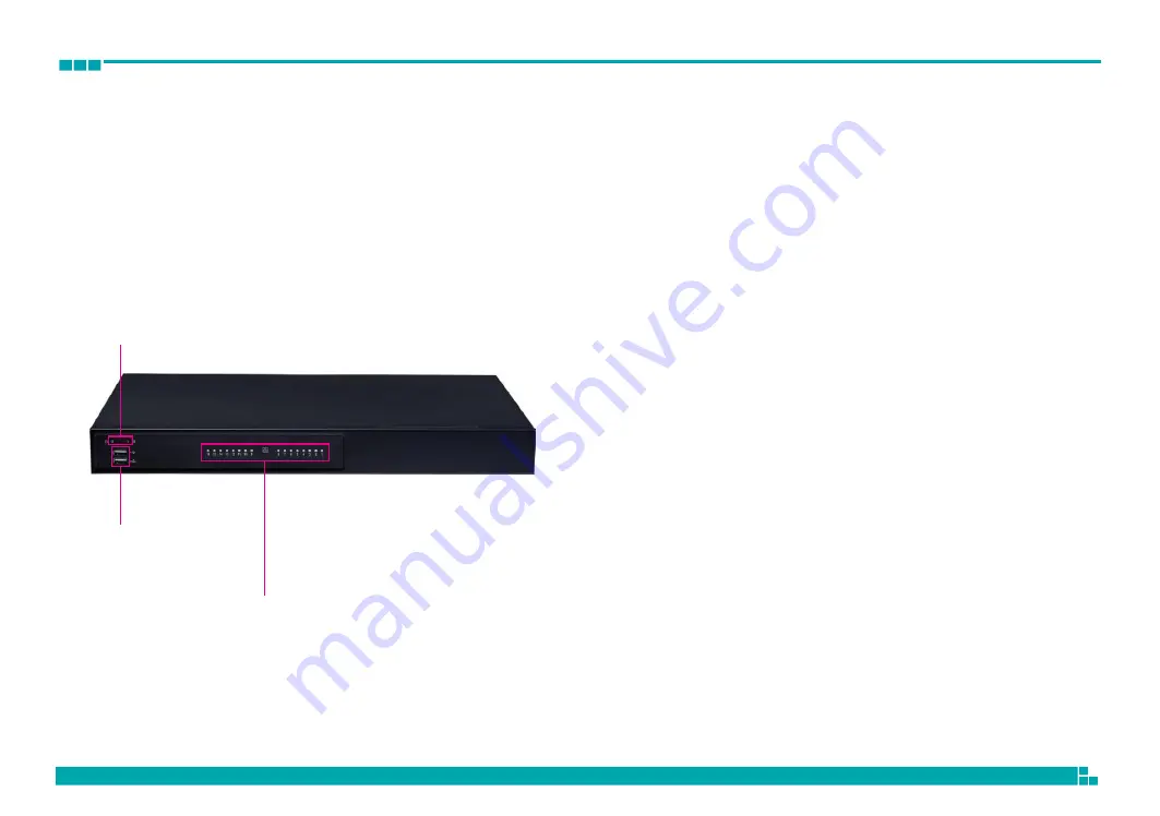
Front Panel 

LED Indicators 

Indicates the power status of the system. 
Indicates the status of the hard drive. 


Dual USB Ports 

Used to connect USB 2.0 devices. 


PoE LAN LED Indicators 

Indicates the status of the LAN ports. 


LED Indicators 


PoE LAN LED Indicators 

2x USB 2.0 Ports 

Содержание NRP14162 Series

Страница 1: ...Video Intelligent Surveillance NRP14162 Series Note The manual is subject to change without notice diviotec com ...

Страница 2: ...nd USB 2 0 Ports 12 DVI I and RS485 Connector 13 HDMI Connector 14 Audio Connectors 14 PoE LAN 8 Ports RJ45 Connector 15 PoE LAN 8 Ports RJ45 Connector 15 Power SW Connector 16 Internal Connectors 17 54V Power In Connector 17 GPIO Connector 17 System Fan 2 18 USB 2 0 Connector 18 HDD PWR LED Wire 19 SATA Connector 19 RAID SATA Connector 20 SATA Power Connector 21 SATA Power Connector 21 SATA Power...

Страница 3: ...4 BIOS Setup About BIOS Setup 43 When to Configure the BIOS 43 Default Configuration 44 Entering Setup 44 Legends 44 BIOS Setup Utility 46 Main 46 Advanced 47 Chipset 55 Security 61 Secure Boot 61 Boot 62 Save Exit 62 ...

Страница 4: ...l Atom processor X series and Intel Celeron J series Max 32GB DDR4 supported Dual display of HDMI and DVI I 2 x 3 5 SATA HDD support RAID 0 1 1 x 2 5 SATA SSD HDD 1 x M 2 2242 SATA SSD 1 x 10 100 1000 Intel Ethernet 1 x 2 5G Intel Ethernet 16 x 10 100 PoE 240W max PSE Support TPM 2 0 onboard Support eMMC onboard option ...

Страница 5: ...lution 4096 x 2160 60Hz 1 x DVI I 1 x UART port RS 232 485 setting from BIOS 1 x Min in 1 x Line Out 1 x MIC Power on off switch 16 x Ethernet PoE port 802 3af at compliance with total 240W max PSE 802 3af support 16 ports 15W 802 3at support 8 ports 30W 1 x 4DI 2DO relay type terminal block or 4DI 4DO GPIO DB15 port option Storage 2 x 3 5 SATA HDD support RAID 0 1 1 x 2 5 SATA HDD or SSD 1 x M 2 ...

Страница 6: ...nt Panel LED Indicators Indicates the power status of the system Indicates the status of the hard drive Dual USB Ports Used to connect USB 2 0 devices PoE LAN LED Indicators Indicates the status of the LAN ports LED Indicators PoE LAN LED Indicators 2x USB 2 0 Ports ...

Страница 7: ... system with USB devices Audio Connectors Line in Line out MIC in Line in Receives audio signal input Line out Provides audio signal output MIC in Used to connect an external microphone 16x PoE LAN Ports RJ45 Connectors Enables communication among network clients and delivers power using the same RJ45 to PoE enabled edge devices Power Switch Power Supply SW Press to power on the device Press for p...

Страница 8: ...Chapter 1 Product Introduction 5 430 00 478 00 92 00 92 00 22 00 106 00 Mechanical Dimensions Rackmount Model 6 15 15 85 15 85 465 50 6 50 44 50 49 50 ...

Страница 9: ...Chapter 1 Product Introduction 6 348 00 347 00 430 00 49 50 44 50 430 00 Mechanical Dimensions Desktop Model ...

Страница 10: ...Chapter 1 Product Introduction 7 50 50 44 50 Mechanical Dimensions Wallmount Model 430 00 60 00 348 00 160 00 347 00 60 00 86 00 106 00 443 80 457 80 ...

Страница 11: ...onents by touching a metal object Static electricity can damage many of the electronic components Humid environments tend to have less static electricity than dry environments A grounding strap is warranted whenever danger of static electricity exists Precautions Computer components and electronic circuit boards can be damaged by discharges of static electricity Working on computers that are still...

Страница 12: ... are placed on the correct pins When the jumper cap is placed on both pins the jumper is short If you remove the jumper cap or place the jumper cap on just one pin the jumper is open Refer to the illustrations below for examples of what the 2 pin and 3 pin jumpers look like when they are short on and open off Two Pin Jumpers Open Left and Short Right Three Pin Jumpers Pins 1 and 2 are Short ...

Страница 13: ... Jumpers and Connectors 10 Locations of the Jumpers and Connectors The figure below shows the location of the jumpers and connectors FAN2 CN3 CN1 CN2 PWR_SW1 CN14 CN15 CN12 CN11 CN10 CN9 CN8 CN7 CN6 CN5 CN4 JP1 ...

Страница 14: ...Chapter 2 Jumpers and Connectors 11 Jumpers Clear CMOS Connector type 1x3 3 pin header Connector location JP1 1 3 Pin Settings 1 2 Normal 2 3 Clear CMOS 1 2 On default ...

Страница 15: ...nnector and USB 2 0 Ports Connector type RJ45 port with LEDs Dual USB2 0 ports Connector location CON4 ACT LINK Link Status Steady Green 1Gbps network link Steady Orange 100Mbps network link Off 10Mbps or no link Link Status Steady Green 2 5Gbps network link Steady Orange 1000Mbps network link Off 100Mbps or no link Act Status Yellow Data activity Off No activity Act Status Yellow Data activity Of...

Страница 16: ...GND 16 DVI_HPD_C 17 DVI_D0_N 18 DVI_D0_P 19 GND 20 VGA_DDCCLK_C 21 VGA_DDCDATA_C 22 GND 23 DVI_CK_P 24 DVI_CK_N 25 SP1_DCD_N 26 SP1_RXD 27 SP1_TXD 28 SP1_DTR_N 29 GND 30 SP1_DSR_N 31 SP1_RTS_N 32 SP1_CTS_N Pin Definition Pin Definition 33 SP1_R1_N C1 VGA_RED_C C2 VGA_GREEN_C C3 VGA_BLUE_C C4 VGA_HSYNC_C C5A VGA_GND C5B GND DVI I and RS485 Connector Connector location CON1 25 29 30 33 1 8 17 24 C1 ...

Страница 17: ...tion AUDIO1 Line in 19 1 Line out 18 2 Mic in Pin Definition Pin Definition 1 HDMI_TX2_DP_CM 2 GND 3 HDMI_TX2_DN_CM 4 HDMI_TX1_DP_CM 5 GND 6 HDMI_TX1_DN_CM 7 HDMI_TX0_DP_CM 8 GND 9 HDMI_TX0_DN_CM 10 HDMI_CLK_DP_CM 11 GND 12 HDMI_CLK_DN_CM 13 NC 14 NC 15 HDMI_RT_SCL_SNK 16 HDMI_RT_SDA_SNK 17 GND 18 V5P0_HDMI 19 HDMI_RT_HPD_SNK ...

Страница 18: ...Connector type Phone Jack RJ45 2x4 Port PoE Connector location CON5 PoE LAN 8 Ports RJ45 Connector Connector type Phone Jack RJ45 2x4 Port PoE Connector location CON6 10 12 14 16 8 1 1 8 8 1 1 8 8 1 1 8 8 1 1 8 9 11 13 15 2 4 6 8 8 1 1 8 8 1 1 8 8 1 1 8 8 1 1 8 1 3 5 7 ...

Страница 19: ...Chapter 2 Jumpers and Connectors 16 Power SW Connector Connector type 1x2 2 pin header Connector location PWR_SW1 1 2 Pin Definition Pin Definition 1 GND 2 PWRBTN_N ...

Страница 20: ...CK IN P Pin Definition Pin Definition 1 5 0V 2 GND 3 GPIO80 4 GPIO84 5 GPIO81 6 GPIO85 7 GPIO82 8 GPIO86 9 GPIO83 10 GPIO87 Internal Connectors 54V Power In Connector Connector type 2x2 4 pin header Connector location CN11 GPIO Connector Connector type 2x5 10 pin header Connector location CN5 10 9 2 4 1 3 2 1 ...

Страница 21: ..._PWM Pin Definition Pin Definition 1 V5P0_USB2_HDR 2 V5P0_USB2_HDR 3 USB2_4_DN_CM 4 USB2_5_DN_CM 5 USB2_4_DP_CM 6 USB2_5_DP_CM 7 GND 8 GND 9 X 10 N C System Fan 2 Connector type 1x4 4 pin header Connector location FAN2 USB 2 0 Connector Connector type 2x5 10 pin header Connector location CN15 10 9 1 4 2 1 ...

Страница 22: ... 2 LED_PWR_LOGIC_N 3 LED_HDD_LOGIC_N 4 LED_HDD_PU Pin Definition Pin Definition 1 GND 2 SATA_CON2_TXP 3 SATA_CON2_TXN 4 GND 5 SATA_CON2_RXN 6 SATA_CON2_RXP 7 GND HDD PWR LED Wire Connector type 1x4 4 pin header Connector location CN14 SATA Connector Connector location CN1 4 1 7 1 ...

Страница 23: ...CON1_TXP 3 RSATA_CON1_TXN 4 GND 5 RSATA_CON1_RXN 6 RSATA_CON1_RXP 7 GND Pin Definition Pin Definition 1 GND 2 RSATA_CON2_TXP 3 RSATA_CON2_TXN 4 GND 5 RSATA_CON2_RXN 6 RSATA_CON2_RXP 7 GND RAID SATA Connector Connector location CN7 RAID SATA Connector Connector location CN6 7 1 7 1 ...

Страница 24: ...1 V12P0_SATA 2 GND 3 GND 4 V5P0_SATA Pin Definition Pin Definition 1 V12P0_RAID_1 2 GND 3 GND 4 V5P0_RAID_1 SATA Power Connector Connector type 1x4 4 pin header Connector location CN2 SATA Power Connector Connector type 1x4 4 pin header Connector location CN8 4 1 4 1 ...

Страница 25: ...Chapter 2 Jumpers and Connectors 22 SATA Power Connector Connector type 1x4 4 pin header Connector location CN9 4 1 Pin Definition Pin Definition 1 V12P0_RAID_0 2 GND 3 GND 4 V5P0_RAID_0 ...

Страница 26: ...ECTOR KEY 18 CONNECTOR KEY 19 CONNECTOR KEY 20 NC 21 NC 22 NC 23 NC 24 NC 25 NC 26 NC 27 GND 28 NC 29 NC 30 NC 31 NC 32 NC Pin Definition Pin Definition 33 GND 34 NC 35 NC 36 NC 37 NC 38 SATA_DEVSLP0 39 GND 40 NC 41 M2_SATA_RP 42 NC 43 M2_SATA_RN 44 NC 45 GND 46 NC 47 M2_SATA_TN 48 NC 49 M2_SATA_TP 50 NC 51 GND 52 NC 53 NC 54 NC 55 NC 56 MFG_DATA 57 GND 58 MFG_CLK 59 NC 60 NC 61 NC 62 NC 63 NC 64 ...

Страница 27: ... and the deployment of Group A and Group B are independent and cannot be mixed For the following example the PoE switch deployment guidance will be based on group A and Group B PoE Switch Connecter Define Rear IO PoE Switch LED Indicator Status Front Side When the cable is plugged into the PoE port and if the device is detected then the LED will indicate the corresponding port When PoE overload 12...

Страница 28: ...and Connectors 25 2 AT Mode Condition 1 Group A Port 1 2 3 4 2 4 6 8 Condition 2 Group A Port 3 4 5 6 1 3 5 7 Group B Port 9 10 11 12 Group B Port 11 12 13 14 10 12 14 16 9 11 13 15 10 12 14 16 2 4 6 8 1 3 5 7 9 11 13 15 ...

Страница 29: ...nd Connectors 26 Condition 3 Group A Port 5 6 7 8 3 AF AT Multi mode Condition 1 Group A 1AT 6AF 2 4 6 8 1 3 5 7 Group B Port 13 14 15 16 Group B Port 1AT 6AF 10 12 14 16 9 11 13 15 2 4 6 8 1 3 5 7 10 12 14 16 9 11 13 15 ...

Страница 30: ...Chapter 2 Jumpers and Connectors 27 Condition 2 Group A 2AT 4AF Condition 3 Group A 3AT 2AF 2 4 6 8 1 3 5 7 2 4 6 8 1 3 5 7 Group B 2AT 4AF Group B 3AT 2AF 10 12 14 16 9 11 13 15 10 12 14 16 9 11 13 15 ...

Страница 31: ...l Monitor USB2 0 x2 eSPI PCIe Gen2 x 1 PCIe Gen2 x 1 USB 2 0 x 2 MDI MDI USB 3 2 Gen 2 x 2 Type A USB 2 0 x 2 POE1 RGMII Smart FAN Control Type A x 1 Transformer IP1001C 8 x 10 100 TP Port RJ45 MCU 2 4 6 8 1 3 5 7 10 12 14 16 9 11 13 15 GPIO 4 In 4 Out EEPROM IP808AR 48 MQFN EEPROM IP403 Power Supply 3 3V 1 1V 3 3V 2 5V USB 3 1 Gen 2 x 2 USB 2 0 x 2 SATA 3 0 SATA 3 0 2 5 HDD SATA 3 0 CH7157A BFI D...

Страница 32: ...e Chassis Cover Prior to removing the chassis cover make sure the unit s power is off and disconnected from the power sources to prevent electric shock or system damage 1 Remove the 5 screws on the system s top cover 2 Remove the top cover C CA AU UT TI IO ON N ...

Страница 33: ...Chapter 3 System Setup 30 Complete ...

Страница 34: ...Chapter 3 System Setup 31 Installing the 3 5 HDD 1 Remove the HDD bracket ...

Страница 35: ...Chapter 3 System Setup 32 2 Set 3 5 HDD into the HDD bracket Use 6 32 type screw 6 32 screw x4 3 5 HDD lock on bracket ...

Страница 36: ...ug in the HDD SATA cable and SATA power cable lock the screw into the system 4 Remove the HDD bracket Left Note HDD SATA cable should be installed at CN6 of the mainboard SATA power cable should be installed at CN8 of the mainboard ...

Страница 37: ...Chapter 3 System Setup 34 5 Set 3 5 HDD into the HDD bracket use 6 32 type screw 6 32 screw x4 3 5 HDD lock on bracket ...

Страница 38: ...Chapter 3 System Setup 35 6 Set 2 5 SSD into the HDD bracket use M3 type screw M3 screw x4 2 5 HDD lock on bracket ...

Страница 39: ...g in the SSD SATA cable and SATA power cable Note HDD SATA cable should be installed at CN7 of the mainboard SATA power cable should be installed at CN9 of the mainboard Note 2 5 SSD HDD SATA cable should be installed at CN1 of the mainboard 2 5 SSD HDD SATA power cable should be installed at CN2 of the mainboard ...

Страница 40: ...Chapter 3 System Setup 37 9 Tightening the cable for 2 5 SSD ...

Страница 41: ...Chapter 3 System Setup 38 9 Tightening the cable for 3 5 SSD Complete ...

Страница 42: ...il they slip into the sockets Installing Memory SO DIMM Use DDR4 SO DIMM 1 Locate the DIMM memory sockets 2 Release the locks on the DIMM memory sockets Insert the modules into the sockets at a 90 degree angle Apply firm even pressure to each end ...

Страница 43: ...m Setup 40 3 Release the locks on the second DIMM memory sockets Insert the other module into the sockets also at a 90 degree angle Apply firm even pressure to each end of the modules until they slip into the sockets ...

Страница 44: ...etup 41 Installing M 2 SSD 1 First remove the screw on the board 2 Insert the M 2 SSD into the M 2 slot at a 45 degree angle until the gold plated connector on the edge of the module completely dissapears inside the slot ...

Страница 45: ...Chapter 3 System Setup 42 3 With the module fully inserted tighten a screw into the mounting hole on the module to secure it 4 Complete ...

Страница 46: ...CMOS With easy to use pull down menus you can configure such items as Hard drives diskette drives and peripherals Video display type and display options Password protection from unauthorized use Power management features The settings made in the setup program affect how the computer performs It is important therefore first to try to understand all the setup options and second to make settings appr...

Страница 47: ... If the error occurs before the display device is initialized a series of beeps will be transmitted If the error occurs after the display device is initialized the screen will display the error message Powering on the computer and immediately pressing Del allows you to enter Setup Legends Press the key to enter Setup Key Function Moves the highlight left or right to select a menu Moves the highlig...

Страница 48: ... available fields not shown on the screen Use the up and down arrow keys to scroll through all the available fields Submenu When appears on the left of a particular field it indicates that a submenu which contains additional options are available for that field To display the submenu move the highlight to that field and press ...

Страница 49: ...om 1999 to 2099 System Time The time format is hour minute second The time is based on the 24 hour military time clock For example 1 p m is 13 00 00 Hour displays hours from 00 to 23 Minute displays minutes from 00 to 59 Second displays seconds from 00 to 59 BIOS Information BIOS Vendor Product Name BIOS Version Build Date and Time American Megatrends NRP14162 Series RN14 003 x64 10 12 2021 14 20 ...

Страница 50: ...N A Supported Not Supported When enabled a VMM can utilize the additional hardware capabilities provided by Vanderpool Technology Intel VMX Virtualization Technol Enabled Select Screen Select Item Enter Select Change Opt F1 General Help F2 Previous Values F3 Optimized Defaults F4 Save Exit ESC Exit Intel VMX Virtualization Technology When this field is set to Enabled the VMM can utilize the additi...

Страница 51: ...trol P0 Fused Max Core Ratio P1 Fused Max Core Ratio P2 Fused Max Core Ratio P3 Fused Max Core Ratio Boot performance mode Intel R Speedstep tm Race to Halt RTH Intel R Speed Shift Technology C states N A N A N A N A Max Non Turbo Perf Enabled Enabled Enabled Disabled Select the performance state that the BIOS will set starting from reset vector Select Screen Select Item Enter Select Change Opt F1...

Страница 52: ...SHA256 SHA 1 SHA256 Enables or Disables BIOS support for security device O S will not show Security Device TCG EFI protocol and INT1A interface will not be available SHA 1 PCR Bank SHA256 PCR Bank Disabled Enabled Pending operation Platform Hierarchy Storage Hierarchy Endorsement Hierarchy TPM 2 0 UEFI Spec Version Physical Presence Spec Version TPM 2 0 InterfaceType Device Select None Enabled Ena...

Страница 53: ... Presence Spec Version Select to tell O S to support PPI Spec Version 1 2 or 1 3 Note some HCK tests might not support 1 3 Device select TPM 1 2 will restrict support to TPM 1 2 devices TPM 2 0 will restrict support to TPM 2 0 devices Auto will support both with the default set to TPM 2 0 devices if not found TPM 1 2 devices will be enumerated NCT5525D Super IO Configuration This section is used t...

Страница 54: ...board Serial Port Mode This field is used to configure the mode of serial port as RS232 or RS485 Change Settings Select an optimal settings for Super IO Device Hardware Monitor This section is used to monitor hardware such as temperature fan speed and voltages PC Health Status Smart Fan function setting System temperature1 48 c System Fan Speed 8035 RPM 5V 5 117 V 12V 12 096 V Smart Fan Function S...

Страница 55: ... time The amount of time fan takes to decrease its value by one step Units are intervals of 0 1 second System Fan Setting Fan control mode select System Fan mode SMART FAN IV Step up time 10 Step down time 10 Temperature 1 25 Temperature 2 35 Temperature 3 45 Temperature 4 55 FD RPM 1 140 FD RPM 2 170 FD RPM 3 200 FD RPM 4 230 Critical temperature Critical tolerance Enable critical duty 60 0 Disab...

Страница 56: ...ion is used to configure USB parameters USB Configuration USB Devices 3 Keyboards 1 Mouse Legacy USB Support Enabled XHCI Hand off Enabled USB Mass Storage Driver Support Enabled USB hardware delays and time outs USB transfer time out 20 sec Device reset time out 20 sec Device power up delay Auto Enables Legacy USB support AUTO option disables legacy support if no USB devices are connected DISABLE...

Страница 57: ...ime out Device Power up Delay Maximum time the device will take before it properly reports itself to the Host Controller Auto uses default value for a Root port it is 100ms for a Hub port the delay is taken from Hub descriptor Network Stack This section is used to configure the network stack Network Stack Disabled Enable or Disable UEFI Network Stack Select Screen Select Item Enter Select Change O...

Страница 58: ...e Exit ESC Exit SDIO Access Mode Auto option Access SD device in DMA mode if controller supports it otherwise in PIO mode DMA option Access SD device in DMA mode PIO option Access SD device in PIO mode eMMC DA4032 31 2GB Mass storage device emulation type Auto enumerates devices less than 530MB as floppies Forced FDD option can be used to force HDD formatted drive to boot as FDD Chipset This secti...

Страница 59: ...ize 4096 MB Unknown Number of Ranks 1 Manufacturer Kingston Channel 1 Slot 1 Not Populated Disab Memory ratio reference clock optio Safe Mode Support Disabled Maximum Memory Frequency Auto Safe Mode enable support Option will be used for changes WAS that may affect an stable MRC Select Screen Select Item Enter Select Change Opt F1 General Help F2 Previous Values F3 Optimized Defaults F4 Save Exit ...

Страница 60: ...c Memory size used by the IGD DiSM Size Configures the DiSM Size for 2LM SKu Graphics Turbo IMON Current Configures the graphics turbo IMON value The supported range is 14 to 31 Internal Graphics Keep IGFX enabled based on the setup options Version 2 21 1278 Copyright C 2021 AMI Chipset Aptio Setup AMI Graphics Configuration Graphics Turbo IMON Current 31 Internal Graphics Auto GTT Size 8MB Apertu...

Страница 61: ...reen Select Item Enter Select Change Opt F1 General Help F2 Previous Values F3 Optimized Defaults F4 Save Exit ESC Exit PCH IO Configuration This section is used to configure PCH IO configuration SATA Configuration This section is used to configure the SATA device option settings Aptio Setup AMI Aptio Setup AMI Main Advanced Chipset Security Boot Save Exit Main Advanced Chipset Security Boot Save ...

Страница 62: ... USB Overcurrent Enabled USB Overcurrent Lock Enabled USB Port Disable Override Disabled Option to enable Compliance Mode Default is to disable Compliance Mode Change to enabled for Compliance Mode testing USB Device HOST Mode Override Disabled USB UCSI ACPI device Disabled Select Screen Select Item Enter Select Change Opt F1 General Help F2 Previous Values F3 Optimized Defaults F4 Save Exit ESC E...

Страница 63: ... enable or disable the corresponding USB port from reporting a device connection to the controller USB Device HOST Mode Override Selectively enable or disable the corresponding USB 2 0 and USB 3 0 port device mode USB UCSI ACPI device Enables or disables USB UCSI ACPI device PCH IO Configuration This section is used to configure PCH IO configuration PCH IO Configuration SATA Configuration USB Conf...

Страница 64: ...C Exit System Mode Setup Secure Boot Enabled Not Active Secure Boot Mode Standard Restore Factory Keys Reset to Setup Mode Key Management Secure Boot feature is Active if Secure Boot is Enabled Platform Key PK is enrolled and the System is in User mode The mode change requires platform reset Select Screen Select Item Enter Select Change Opt F1 General Help F2 Previous Values F3 Optimized Defaults ...

Страница 65: ...st the boot sequence of the system Boot Option 1 is the first boot device that the system will boot from next will be 2 and so forth Fast Boot When enabled the BIOS will shorten or skip some check items during POST This will decrease the time needed to boot the system Save Exit Save Changes and Reset Discard Changes and Reset Restore Defaults Exit the system after saving the changes Select Screen ...

Страница 66: ...D SETUP Hardware Setup NRP14162 have RAID 0 1 SPAN mode to enhance the storage management function Before setting the RAID function you must complete the HDD installation first the corresponding port number as below HDD Port No SATA Channel P0 CN7 P1 CN6 ...

Страница 67: ...mediately press Ctrl R to access the RAID Manager Tool UI Here the user may start building the RAID function on the system RAID Program Main Menu The main menu allows you to select from several setup functions Use arrow keys to select among the items and press to enter to select the function ...

Страница 68: ...rrently being rebuilt The user s data is accessible Rebuild Failed The target of the rebuild operation failed but the user s data is still available Another rebuild can be attempted Verify Failed The target of the verify operation failed but the user s data is still available Another rebuild or verify can be attempted Rebuilding Paused The target of the rebuild operation was paused The user s data...

Отзывы: