


9
4.4 Principles of Operation
This product is designed to capture and clean smoke and dust from medium & heavy duty welding, soldering, and grinding applications. When operating,
air is drawn in to the nozzle, passes through the 7” diameter hose, then through the air cleaner’s filtration system, and is exhausted through the rear
discharge.
This product consists of four basic components:
1.
Capture Arm(s)
2.
A blower
3.
Cartridge Filter
4.
Motor & Electrical assemblies
5. ICS-360 Injection Cleaning System
6. Dust Drawer (Mobile) or Hopper (Ceiling Mount)
• The operator is to positon the machine within operating distance, and activate the caster wheel brakes.
• The operator can then position the capture arm close enough to the worksite to capture all dust and fumes that will be produced.
• Ensuring that all safety procedures have been followed, the operator can turn on the machine and begin working.
• When not in use, the machine should be turned off.
4.5 Failure Event
4.6 ICS-360 Injection Cleaning System
If, for some reason, during operation there is an accident, a blockage occurs, the Minihelic displays abnormal pressure differences, or the machine begins to act
abnormally, the operator should immediately shut off the machine. This is considered a machine failure and the following steps should be taken:
This product consists of four basic components:
1.
Turn the power switch to the OFF position.
3.
Seek medical attention if an accident occurred.
4.
Follow the guidelines in SECTION 5: Maintenance and Troubleshooting.
Remember, under no circumstance should the machine be turned back on while performing maintenance.
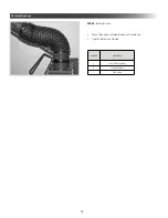
The ICS-360 Injection Cleaning System works to blow particulate off the filter and into the dust drawer in a cycle that takes approximately 8 minutes to complete.
The cycle initiates automatically each time the units turned off. If the cycle has started and the unit is turned back on, the ICS-360 will recommence cleaning from the
last position the next time the unit switched off.
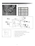
STATUS LIGHTS
A
Fault Alert
B
Solid > Cleaning
Flashing > Homing
C
Trigger
D
Top Switch
E
Bottom Switch
F
Motor Up
G
Motor Down
H
Solenoid 1
I
Solenoid 2
J
Power 12VAC
Содержание FRED SR
Страница 22: ...22 NOTES...
Страница 23: ...NOTES 23...


