background image

8 / 16

Setting the Communicating Sensor Subnet ID

Controllers can be commissioned with an Allure EC-Smart-Vue sensor.

The default Subnet ID for an Allure EC-Smart-Vue Series Communicating Sensor is 1. To commission an ECB Series controller, the sensor’s Subnet ID
must be set to 1. If the sensor’s Subnet ID has been set to another value (for example, the display flashes error code 1 with the Bell icon when the sen-
sor is connected to a controller for commissioning), change the Subnet ID to 1 as follows:

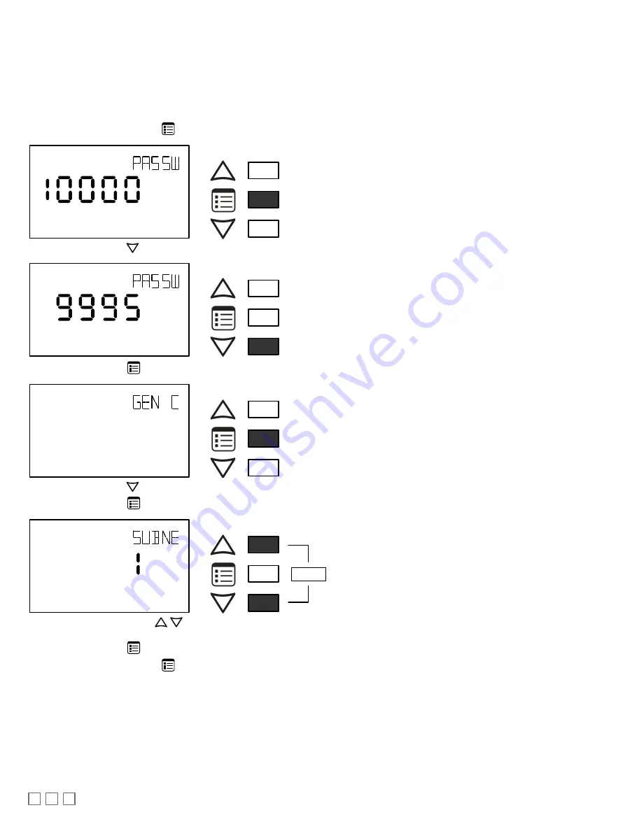
1. Connect an an Allure EC-Smart-Vue Series Communicating Sensor to the controller with a Cat 5e patch cable. Wait for the Bell icon and the number

1 to flash on the display.

2. Press and hold the Menu button 

 for 5 seconds to enter the password menu. 10000 is shown on the display.

OR

Screen Timeout: 15 seconds

3. Press the down button 

 to set the number to 9995 (this is the default password).

OR

Screen Timeout: 15 seconds

4. Press the Menu button 

 to submit the password. Upon submitting the password, the GEN CFG menu appears on the display.

OR

Screen Timeout: 30 seconds

5. Press the down button 

 once to enter the GEN CFG submenu.

6. Press the Menu button 

 several times until SUBNET ID appears on the display. The current controller’s Subnet ID is shown.

OR

Screen Timeout: 30 seconds

7. Use the up and down buttons 


 to set the controller’s Subnet ID to 1. 

Tip

: Hold down either the up or down button to fast-advance the display

value.

8. Press the Menu button 

 once.

9. Press and hold the Menu button 

 for 5 seconds to exit the configuration menu.

The an Allure EC-Smart-Vue Series Communicating Sensor can now be used to go from one ECB series controller to the next for commissioning pur-
poses.

Commissioning Controllers

For  ECB  series  controllers:  to  commission  a  controller  with  a  MAC  Address  DIP  switch  located  on  the  faceplate  or  under  the  cover  in  the  case  of  an
ECB-VAV Series controller, first set the DIP switch to 0 (all off). When using an Allure EC-Smart-Vue sensor for commissioning a controller (before code
is downloaded to the controller from EC-

gfx

Program), connect an Allure EC-Smart-Vue sensor to the controller with its Subnet ID set to 1. (see Setting

the Allure EC-Smart-Vue Sensor Subnet ID).

Содержание Allure EC-Smart-Vue Series

Страница 1: ...Allow for proper clearance around the device s enclosure and wiring terminals to provide easy access for hardware configuration and maintenance Orient the device with the ventilation slots towards the...

Страница 2: ...Mounting pg 3 2 Open the device by pressing in the two 2 tabs on the bottom of the device and pulling the bottom side of the front plate out 3 Set any jumpers see Connector and Jumper Location Identif...

Страница 3: ...Smart Vue Sensor Equipped with a CO Sensor The Allure EC Smart Vue C CM CH CHM sensors are factory calibrated to accurately read CO2 concentration levels at sea level When these Allure EC Smart Vue se...

Страница 4: ...U 4 1 to 4 ECB 300 ECL 300 ECB 400 Series ECL 400 Series ECB 600 Series ECL 600 Series ECY S1000 Series 12 1 to 12 Table 1 Number of Allure EC Smart Vue sensors supported by controller model 1 A contr...

Страница 5: ...ECx 400 Series Subnetwork Bus A controller can support a maximum of two Allure EC Smart Vue sensor models equipped with a CO2 sensor the remaining connected models must be without a CO2 sensor See Tab...

Страница 6: ...us ON EOL OFF Controller Series ECB VAV O ECB VAVS ECB VVTS ECB VAV N ECB 103 ECB 203 Series ECB 300 Series ECB 400 Series Back of Allure EC Smart Vue ECL VAV O ECL VAVS ECL VVTS ECL VAV N ECL 103 ECL...

Страница 7: ...OFF ON EOL OFF EOL ON Typical Compatible Controller I O Extension Modules ECx 4xx ECx 4xx I O Extension Modules 2 Wire Shielded Last daisy chained I O Extension Module EOL Jumper is ON All other I O E...

Страница 8: ...the GEN CFG menu appears on the display OR Screen Timeout 30 seconds 5 Press the down button once to enter the GEN CFG submenu 6 Press the Menu button several times until SUBNET ID appears on the disp...

Страница 9: ...lay OR Screen Timeout 15 seconds 3 Use the down button to set the number to 9995 this is the default password OR Screen Timeout 15 seconds 4 Press the Menu button to submit the password Upon submittin...

Страница 10: ...r s BAUD rate as follows 1 Connect an Allure EC Smart Vue Series Communicating Sensor sensor to the controller with a Cat 5e patch cable Wait for the display to show the room temperature 2 Press and h...

Страница 11: ...rt Vue sensor equipped with a motion sensor to the controller with a Cat 5e patch cable 2 After a 30 second warm up period if movement is detected the motion sensor light will turn on 3 To test the se...

Страница 12: ...the indicator PIR LED jumper is enabled If you wish to disable it set jumper J18 to Disabled See Connector and Jumper Location Identification and Configuration pg 3 BACnet Network Access from the Sens...

Страница 13: ...work segment should have their Net to Subnet Port Settings jumpers enabled Enabling too many Allure EC Smart Vue sensors with network access may cause network communication issues If there are any net...

Страница 14: ...bled Figure 16 LONWORKS Network Bus Topology To temporarily access the LONWORKS LAN for commissioning and maintenance purposes connect a LONWORKS USB network interface to the audio plug port located o...

Страница 15: ...ve Allure EC Smart Vue sensor firmware that supports the motion sensor When the Allure EC Smart Vue sensor is connected to a controller its firmware is loaded from the controller In this case the cont...

Страница 16: ...sible for using the correct wiring procedures and maintaining safe working conditions with fail safe environ ments Distech Controls reserves the right to change delete or add to the information in thi...

Отзывы: