


Platform: DBALL2
Firmware:
CHRYSLER4
© 2017 Directed. All rights reserved.
Rev.: 20170818
3
2
4
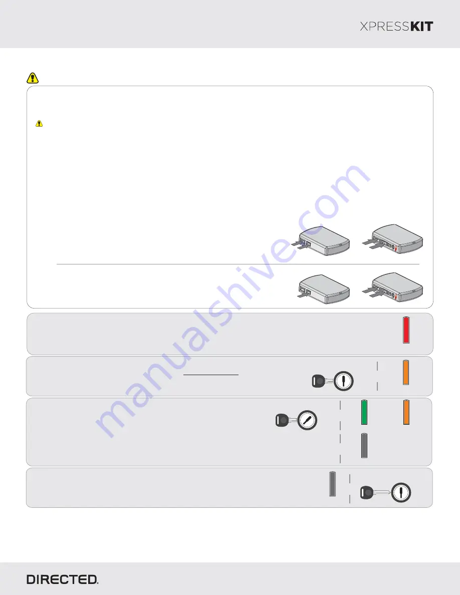
When the green
turns
,
LED
OFF
turn
the key to the
position
OFF
from the ignition barrel.
and
it
remove
Insert
wait
the key into the ignition barrel
and
for
without turning it
the
to flash orange.
LED
Turn
the key to the
position. The
will continue to
ON
LED
flash orange. It will then turn
solid green
orange
ON
OR
for 3 seconds, before turning
.
OFF
Refer to
Diagnostics section
10 for
the
on page
LED
troubleshooting if the
does not turn
solid green
LED
ON
OR
orange within 15 seconds.
&
&
&
Module Programming
Page 9
Flash Orange
&
Off
Off
Key OUT
OFF
START
IGN
Key IN
OFF
START
ON
Key IN
OFF
START
ON
Solid Green Solid Orange
or
You have successfully completed the module programming sequence.
1
Solid
Wait until the LED turns
solid red.
ON
Important
Make all the required connections to the vehicle, as described in the wiring diagram(s) found in this guide, and double check to
ensure everything is correct prior to moving onto the next step.
Warning!
To take advantage of advanced features, you must use Xpress
4.5 (and higher) or the Directechs Mobile app.
VIP
When the flashing operation is successful, you can proceed with the programming instructions below.
Refer to the
Diagnostics section on page
for more information and for troubleshooting purposes.
LED
n
OR
If required for your installation, connect the 10-pin, 12-pin and 14-pin harnesses to
the module, then connect the 4-pin D2D harness.
D2D Installation
W W Installation
2
If required for your installation, connect the 10-pin and 12-pin harnesses to the
module, then connect the 14-pin harness to the module.
10-pin
D2D
1
st
12-pin
14-pin
2
nd
3
rd
10-pin
D2D
1
st
4
th
12-pin
14-pin
2
nd
3
rd
Flashing a module using your computer:
1. Connect the interface module to your computer using the
XKLoader2.
2. Go to www.directechs.com using Internet Explorer, and
select the
button.
Flash Module
3. Follow the instructions to select your vehicle, installation
type, and configure your options.
4. Once you have configured the firmware options, click on the
FLASH
button.
Flashing a module using your smartphone or tablet
1. Connect the interface module to your
oader3.
XKL
2. Launch the Directechs Mobile app on your smartphone or
tablet.
3. Select
and follow the on screen
FLASH YOUR MODULE
instructions.


