


5
© 2009 Directed Electronics. All rights reserved.
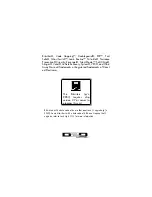
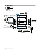
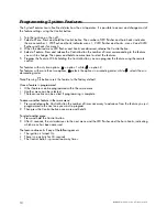
Wiring Diagram
Valet switch
LED
Control button
Status LED
Control Center
Control Center
Control Center
Control Center
Control Center
Valet switch
LED
Control button
Status LED
Control Center
Status LED
Control button
Control Center 6211T
CPU1
10A FUSE
MINI A
TM
RPN: 8540
LIGHT FLASH POLARIT
Y
(10A (M
AXIMUM) FUSE JUMPER)
+ -
5
8
7
6
1
2
3
4
Bitwriter
Port
Neutral Safety
Switch
Horn Input
Polarity Jumper
1
10
9
8
7
6
1
2
3
4
5
1
1
8
5
1
1
3
10
12
18
10
9
1
1
12
D2D Port (for external
Xpresskit interface module)
10A FUSE
MINI ATM
RPN: 8540
LIGHT FLASH POLARITY
(10A (MAXIMUM) FUSE JUMPER)
+ -
ON
IMPORTANT!
Neutral Safety
switch must be plugged in
and in the
ON
position
D2D jumpers; Factory setting is horizontal position.
Most Xpresskit modules use this setting, check the
Xpresskit installation guide for the specific setting.
RF Port
for IVU
Control
Center
Temperature
Sensor
+ -
Main Harness (H1)
(see wiring tables)
H2 Harness
(see wiring tables)
Remote Start (H3)
(see wiring tables)