3
Usage limits (IEC 60974-2)
The cooling device is sized for cooling by means of water cir-
culation in the welder in a continuous manner. As a work cycle,
it is considered at 100%.
Installation
WARNING: CM653.M or CM 589.M may only be installed hor-
izontally.
The installation site for the system must be carefully chosen in
order to ensure its satisfactory and safe use.
The user is responsible for the installation and use of the sys-
tem in accordance with the producer’s instructions contained
in this manual.
Before installing the system the user must take into consider-
ation the potential electromagnetic problems in the work area.
In particular, we suggest that you should avoid installing the
system close to:
•
Signalling, control and telephone cables.
•
Radio and television transmitters and receivers.
•
Computer and control and measurement instruments.
•
Security and protection instruments.
Persons fitted with pace-makers, hearing aids and similar
equipment must consult their doctor before going near a ma-
chine in operation. The installation environment of the device
has to be in conformance with the protection degree of the
carcass, which is equivalent to IP 23 (publication IEC 60529),
which means that the device may be used in closed environ-
ments as well as outdoors. This system is cooled by means of
the forced circulation of air, and must therefore be placed in
such a way that the air may be easily sucked in and expelled
through the apertures made in the frame.
Usage norms
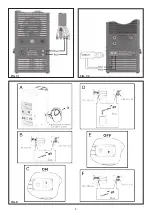
CONTROL APPARATUS (Fig. A)
Pos. 1
Cap for filling tank.
Pos. 2
Level indicator for presence of coolant in the tank (the
level of the liquid must never be inferior to the notch
indicated).
Pos. 3
Luminous two-pole switch.
Pos. 4
Protection fuse.
Pos. 5
CM 589.M: Blue and red quick couplings for connect-
ing the torch.
Pos. 6
CM653.M: Blue and red quick couplings for connect-
ing the torch.
Pos. 7
Cable for electric connection of the device to the gen-
erator cooling device.
Electrical wiring of the
welding cooling device
The cooling device cannot function in an autonomous manner,
therefore it must be connected electrically, in order to operate,
to the welder, making the coupling between the male connec-
tor in the cooling devise and the corresponding female on the
welder (Fig. B).
Prior to beginning, the operator has to assure that close at hand
there is both the welder (example: DIX PI 3506.M) and the cool-
ing device (example: CM 589.M) and that both are working at
the same feed voltage of 400 V.
Upon final connection, even the pressure switch will be con-
nected. The pressure switch has a protective function. It does
not allow the device to emit voltage in case the water pres-
sure and therefore the cooling capacity, is inferior to the cali-
bration value.
FIG. A
FIG. B
Содержание DIX CM 653.M
Страница 5: ...5 FIG C1 FIG C2 FIG D...
Страница 8: ......


